
Temperature controller and temperature control method, and heating wire therefor

a technology of temperature controller and heating cable, which is applied in the direction of temperatue control, process and machine control, instruments, etc., can solve the problems of complex manufacturing process of heating cable, inability to detect the temperature of the overall heating cable, fire and electric shock, etc., and achieve the effect of preventing the emission of harmful electromagnetic waves

Inactive Publication Date: 2006-12-28
KIL JONG JIN
View PDF6 Cites 29 Cited by
  • Summary
  • Abstract
  • Description
  • Claims
  • Application Information

AI Technical Summary

Benefits of technology

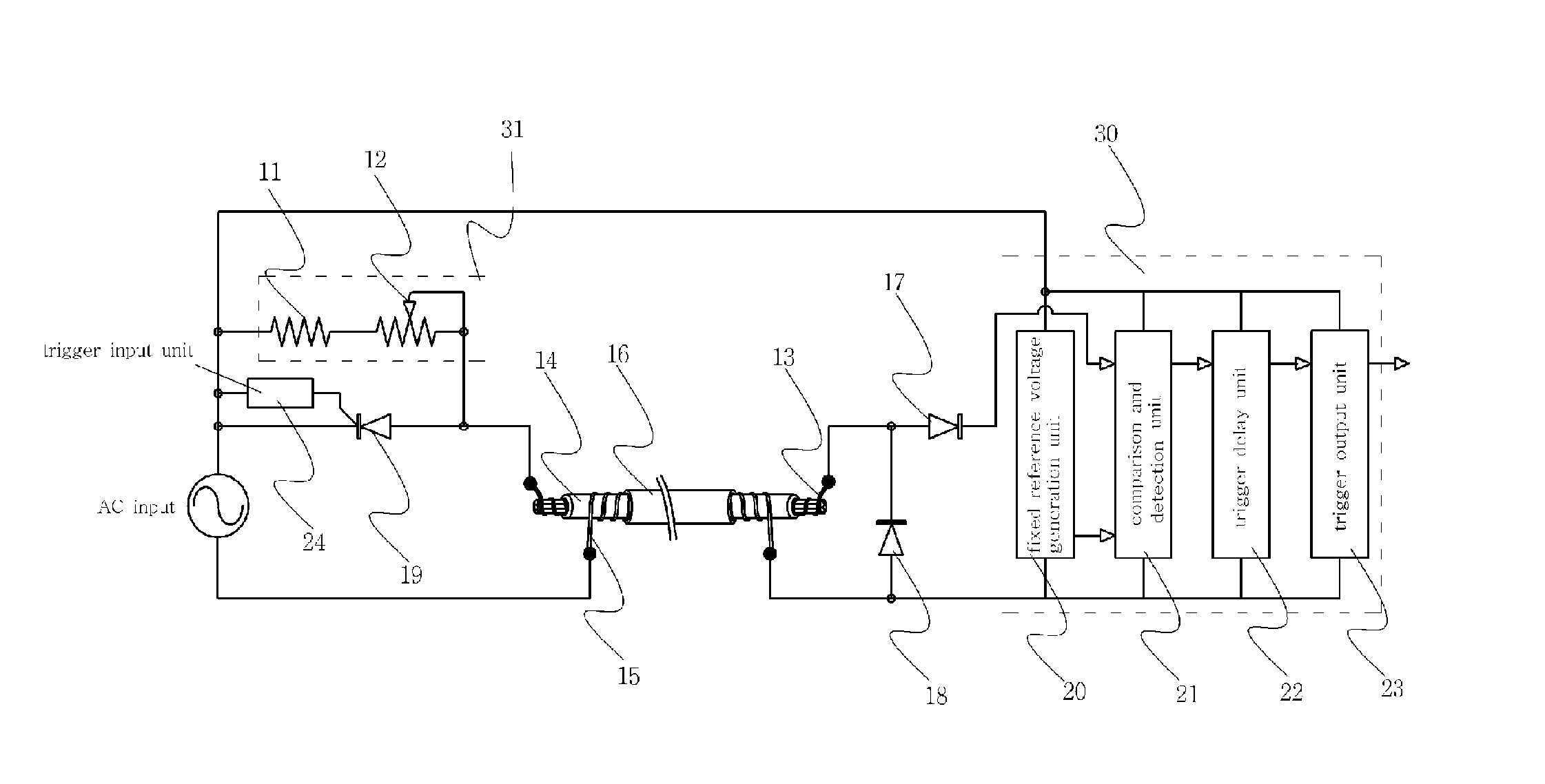
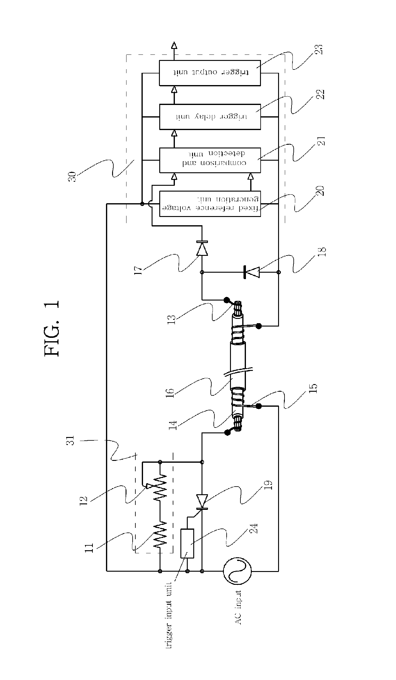
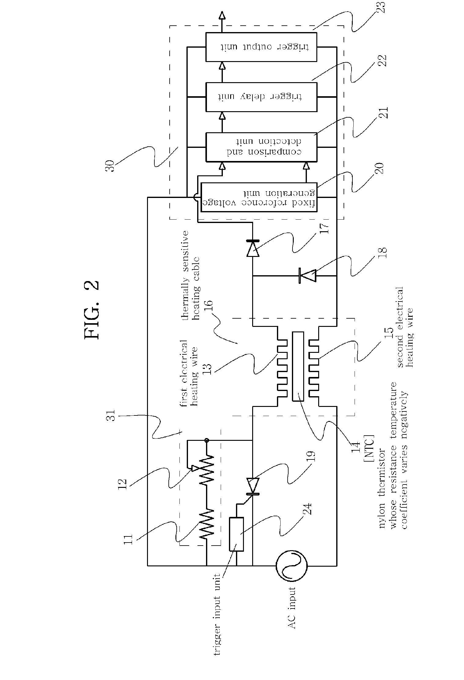
[0011] The present invention has been proposed to overcome the above-described problems, and an object of the present invention is to provide a temperature controller and temperature control method that are capable of performing heating and temperature detection in a non-electromagnetic wave fashion without short-circuiting one end of a heating cable. Another object of the present invention is to provide a temperature controller and temperature control method that are capable of preventing the emission of harmful electromagnetic waves from a heating cable used for bedding, etc.
[0012] Another object of the present invention is to provide a temperature controller and temperature control method that are capable of cutting off the supply of an overcurrent by forcibly cutting a fuse when it is impossible to control the temperature of an electrical heating wire. Another object of the present invention is to provide a temperature controller and temperature control method that are capable of detecting local overheating at an arbitrary location as well as the temperature of the overall electrical heating wire. Furthermore, another object of the present invention is to provide a temperature controller and temperature control method that can ground the surface electric field of the heating cable at a zero electric potential.
[0013] Furthermore, still another object of the present invention is to provide a temperature detection non-electromagnetic wave heating cable that is provided with a thermistor between a first electrical heating layer and a second electrical heating layer, and causes the amount of heat to be automatically reduced by a decrease in the resistance value of the thermistor when the temperature of the heating cable reaches a reference temperature or an arbitrary location of the heating cable is overheated.
[0014] Furthermore, a still another object of the present invention is to provide a non-electromagnetic wave heating cable that can achieve a non-electromagnetic wave state by maintaining low voltage drops at both ends of a second electrical heating layer, enable shield to attenuates and control electric field leakage, and completely intercept a somewhat leakage electric field by coating the circumferential surface of the second electrical heating layer with a separate conductive coating layer, thus simultaneously preventing both magnetic and electric fields.
[0015] Furthermore, the present invention provides a non-electromagnetic wave heating cable, in which a conductive coating layer surrounding a second electrical heating layer is coated, thus fundamentally preventing a leakage electric field.

Problems solved by technology

However, the method in which the temperature sensor and the heating wire are separated from each other is problematic in that it cannot detect the temperature of the overall heating cable caused by an internal short circuit of the heating cable or local overheating at an arbitrary location.
Accordingly, there are problems in that a fire and an electric shock may occur when the heating cable is locally overheated, short-circuited or cut.
However, the method of detecting temperature using a third electric wire without separating a heating cable wire therefrom is problematic in that a temperature sensor layer and a third metallic layer are added to the heating cable and, therefore, the thickness of a non-magnetic field electrical heating wire increases so that it cannot be used for thin bedding, a manufacturing process of a heating cable is complicated, and manufacturing costs increase.
Furthermore, all of the above-described methods have problems in that they have the problem of temperature control of the heating cable, they cannot be used in practice due to the excessive thickness of the heating cable and they cannot intercept harmful electromagnetic waves caused by voltage or current.
The conventional non-magnetic field heating cable has disadvantages in that it is provided with an internal insulation element, so that the thickness of the heating cable is excessive and the flexibility thereof is poor.
Accordingly, the thickness of the conventional heating cable is at least 6 mm, so that problems arise in that the conventional heating cable protrudes and presses a human's body when the heating cable is applied to an electric mat, and it is almost impossible to apply the conventional heating cable to thin bedding, such as electric mats, electric blankets and electric floors, due to the thickness and flexibility of the conventional heating cable.
However, the improved heating cable cannot perform functions of detecting local overheating and accordingly controlling conduction.
When local overheating occurs or the actual temperature exceeds a reference temperature at an arbitrary location of a heating cable of several tens of meters, power is shut off because there is the danger of a fire or a burn.
That is, inconvenience arises in that a plurality of temperature detection devices are additionally provided at arbitrary locations to detect the temperature of a long heating cable.
These temperature detection devices are configured to protrude outside bedding, thus inconveniencing users.
In particular, a problem arises in that it is difficult to attach the temperature detection devices to thin bedding.

Method used


Image

  • Temperature controller and temperature control method, and heating wire therefor
  • Temperature controller and temperature control method, and heating wire therefor
  • Temperature controller and temperature control method, and heating wire therefor

Examples


embodiment 1

[0142]FIGS. 36 and 37 are construction and sectional diagrams of embodiments 1-1 and 1-2 in which a lead wire is used in the second electrical heating layer of the present invention. Referring to FIG. 36, a heating cable includes a core thread 311 made of polyester, an electrical heating wire 312 spirally wound around the outer circumferential surface of the core thread 311 in one direction along a longitudinal direction, a thermistor 313 applied to surround the outer circumferential surfaces of the electrical heating wire 312 and the core thread 311, first and second lead wires 314a and 314b alternately wound around the outer circumferential surface of the thermistor 313 in a double-spiral form, and a synthetic resin insulation coating 315 applied to surround the thermistor 313 and the first and second lead wires 314a and 314b.

[0143] The electrical heating wire 312 is prevented from being short-circuited and, therefore, is not directly connected to the first and second lead wires ...

embodiment 2

[0150]FIGS. 40 and 41 are construction and sectional diagrams of an embodiment 2-1 in which the first electrical heating layer of the present invention is differently constructed and lead wires are used in a second electrical heating layer. FIGS. 42 and 43 are construction and sectional diagrams of an embodiment 2-3 in which the first electrical heating layer of the present invention is differently constructed and a metallic strip is used in a second electrical heating layer.

[0151] Referring to FIG. 40, the construction of the heating cable of the embodiment 2-1 is similar to that of the heating cable of the embodiment 1-1, but is different from that of the heating cable of the embodiment 1-1 in that a metallic electrical heating conductor 321, instead of the synthetic thread and the electrical heating wires wound around the core thread, is used as the first electrical heating layer. The operating principle of the heating cable of the embodiment 1-1 is similar to that of the heatin...

embodiment 3

[0154]FIGS. 44, 45 and 46 are construction and sectional diagrams of embodiments 3-1, 3-2 and 3-3 in which a conducting coating layer is further included outside the second electrical heating layer of the present invention. Referring to FIG. 44, the construction of the heating cable of the embodiment 3-1 is similar to that of the heating cable of the embodiment 1-1, but is different from that of the heating cable of the embodiment 1-1 in that a conducting coating layer 336, surrounding a thermistor layer 333 and second electrical heating layers 334a and 334b around the thermistor layer 333, is further included. The operation principle of the heating cable of the embodiment 3-1 is similar to that of the heating cable of the embodiment 1-1, but has the further effect of interrupting an electric field exposed between the second electrical heating layers 334a and 334b because the conductive coating surrounds the heating cable of the embodiment 1-1. Reference numeral 334a denotes a first...


PUM


Abstract

The present invention relates to a non-electromagnetic wave temperature controller for a heating cable and a method therefor, which can perform heating and temperature detection in a non-electromagnetic fashion without short-circuiting one end of the heating cable that is used in warmers, such as electric floors, electric mats and electric fomentation devices. Furthermore, the present invention relates to a temperature detection non-electromagnetic heating cable and a temperature controller, which can reduce the amount of heat and control temperature without using a separate temperature sensor when the temperature of the heating cable is controlled or an arbitrary portion of the heating cable is overheated, and can prevent a magnetic field from being generated in the heating cable without short-circuiting one end of electrical heating wires and intercept the generation of a leakage electric field.

Description

BACKGROUND OF THE INVENTION [0001] 1. Field of the Invention [0002] The present invention relates to a non-electromagnetic wave temperature controller for a heating cable and a method therefor, which can perform heating and temperature detection in a non-electromagnetic fashion without short-circuiting one end of the heating cable that is used in warmers, such as electric floors, electric mats and electric fomentation devices. Furthermore, the present invention relates to a temperature detection non-electromagnetic heating cable and a temperature controller, which can reduce the amount of heat and control temperature without using a separate temperature sensor when the temperature of the heating cable is controlled or an arbitrary portion of the heating cable is overheated, and can prevent a magnetic field from being generated in the heating cable without short-circuiting one end of electrical heating wires and intercept the generation of a leakage electric field. [0003] 2. Descript...

Claims


Application Information

Patent Timeline
Patent Type & Authority Applications(United States)
IPC IPC(8): H05B1/02
CPCG05D23/2408H05B2203/01H05B3/56G05D23/1906G05D23/24
Inventor KIL, JONG-JIN
Owner KIL JONG JIN
Learn More