Drive for pivoting a flap arranged on a vehicle body

a technology for driving flaps and vehicle bodies, applied in power-operated mechanisms, door/window fittings, valve details, etc., can solve the problems of increasing power consumption and high cost of self-locking electric motors, and achieve the effect of large transmission ratio

Inactive Publication Date: 2006-12-28
STABILUS
View PDF17 Cites 22 Cited by
  • Summary
  • Abstract
  • Description
  • Claims
  • Application Information

AI Technical Summary

Benefits of technology

[0039] The large transmission ratio which can be achieved is particularly advantageous if the pivot axis extends horizontally.

Problems solved by technology

The use of self-locking electric motors together with clutches is expensive and, on account of the increased resistance of the motor, also requires an increased power consumption.

Method used


Image

  • Drive for pivoting a flap arranged on a vehicle body
  • Drive for pivoting a flap arranged on a vehicle body
  • Drive for pivoting a flap arranged on a vehicle body

Examples


Embodiment Construction

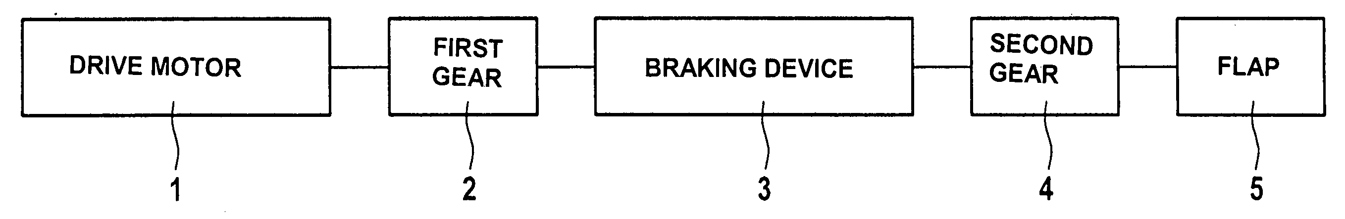
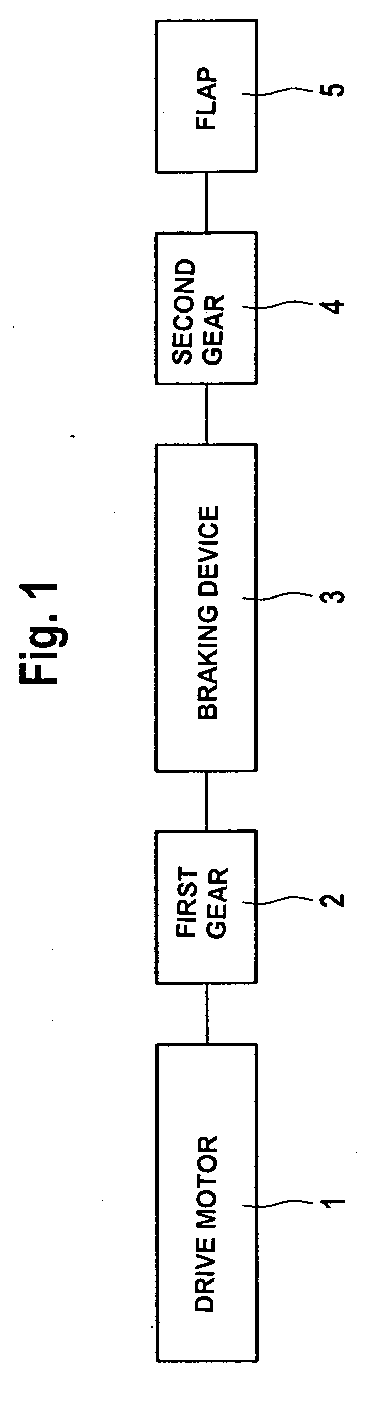
[0043] In the case of the exemplary embodiment in FIG. 1, the hinge of a flap 5 is driven pivotably by a drive motor 1, which is not self-locking, via a drive train composed of a first gear 2, a braking device 3, which is closed in the currentless state, and a second gear 4.

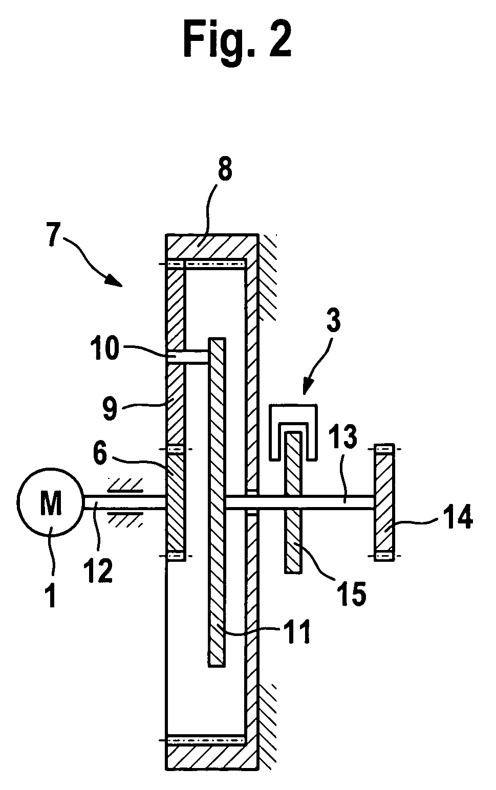
[0044] The drive illustrated in FIG. 2 has a drive motor 1, which is designed as an electric motor, is not self-locking and on the output shaft 12 of which a sun wheel 6 of a planetary gear 7 is fixedly arranged. The sun wheel 6 is surrounded concentrically, with a radial clearance, by a fixed internally toothed rim 8 of the planetary gear 7.

[0045] A planet wheel 9 arranged between the sun wheel 6 and the internally toothed rim 8 engages both in the teeth of the sun wheel 6 and in the teeth of the internally toothed rim 8.

[0046] The planet wheel 9 is mounted rotatably on a journal 10 of a planet carrier 11 which is connected fixedly to a shaft 13 which is coaxial with the output shaft 12 of the drive motor 1 a...


PUM


Abstract

A drive for pivoting a flap arranged on a vehicle body about a pivot axis includes a non-self locking electric motor and a drive train connecting the motor to the flap. The motor can be switched between a driving active state and a non-driving inactive state, the motor being moveable in the inactive state at least substantially without any resistance. A braking device blocks the drive train in the inactive state of the drive motor and unblocks the drive train in the active state of the motor.

Description

BACKGROUND OF THE INVENTION [0001] 1. Field of the Invention [0002] The invention relates to a drive for pivoting a flap arranged on a vehicle body about a pivot axis, with a drive motor, by means of which the flap can be driven pivotably via a drive train. [0003] 2. Description of the Related Art [0004] In the case of drives of this type which can have an electric motor as the drive motor, the electric motor is designed together with a gear as a self-locking electric motor and interacts with a clutch. [0005] The use of self-locking electric motors together with clutches is expensive and, on account of the increased resistance of the motor, also requires an increased power consumption. SUMMARY OF THE INVENTION [0006] It is therefore the object of the invention to provide a cost-effective drive of the type mentioned at the beginning. [0007] According to the invention in that the drive motor can be switched between a driving active state and a non-driving inactive state, the drive mot...

Claims


Application Information

Patent Timeline
Patent Type & Authority Applications(United States)
IPC IPC(8): F16K31/02F02D11/10F16D65/18
CPCE05F5/00E05Y2201/21E05Y2201/22E05Y2201/246E05Y2201/26E05Y2201/266E05F15/614E05Y2201/462E05Y2201/72E05Y2400/326E05Y2800/112E05Y2900/546E05Y2400/44E05Y2201/434E05F5/025
Inventor RITTER, ANDREAS
Owner STABILUS
Why Eureka
Try Eureka