Device and a method for advanced protection from short circuit current

Inactive Publication Date: 2006-12-28
ROZINE VASSILI +1
View PDF6 Cites 6 Cited by
  • Summary
  • Abstract
  • Description
  • Claims
  • Application Information

AI Technical Summary

Benefits of technology

[0011] The objective of the invention is to create a device able to determine the existence of fault current conditions in a circuit before the actual amplitude of the current reaches its full level; thereby dramatically reducing the time between a fault occurring, the detection of the short circuit current, and the generation of the circuit breaker tripping signal to disconnect the circuit. The device determines if the high rate-of-change of the current is caused by normal circuit variations, such as motor starting or initial load energized current, and does not generate the tripping signal to disconnect the circuit.

Problems solved by technology

In many cases another issue is also very important.
This is a protection selectivity (coordination) problem.
In some distribution systems, such as emergency systems, this situation is not acceptable and actions have to be taken to avoid it.
This is usually expensive and this solution increases the thermal stress on the system during a fault.
Depending on the characteristics of the circuit, such current limiting devices can be expensive and heavy pieces of equipment.
Protection relays with this control philosophy exist, but the use of these devices is limited to special applications.
The presence of a motor load or a step load makes this type of protection unreliable.
The conditions of the operation depend on the parameters of the circuit and very often there is no way to distinguish between the initial current of an electric motor starting or initial load current and a fault current.

Method used


Image

  • Device and a method for advanced protection from short circuit current
  • Device and a method for advanced protection from short circuit current
  • Device and a method for advanced protection from short circuit current

Examples


Embodiment Construction

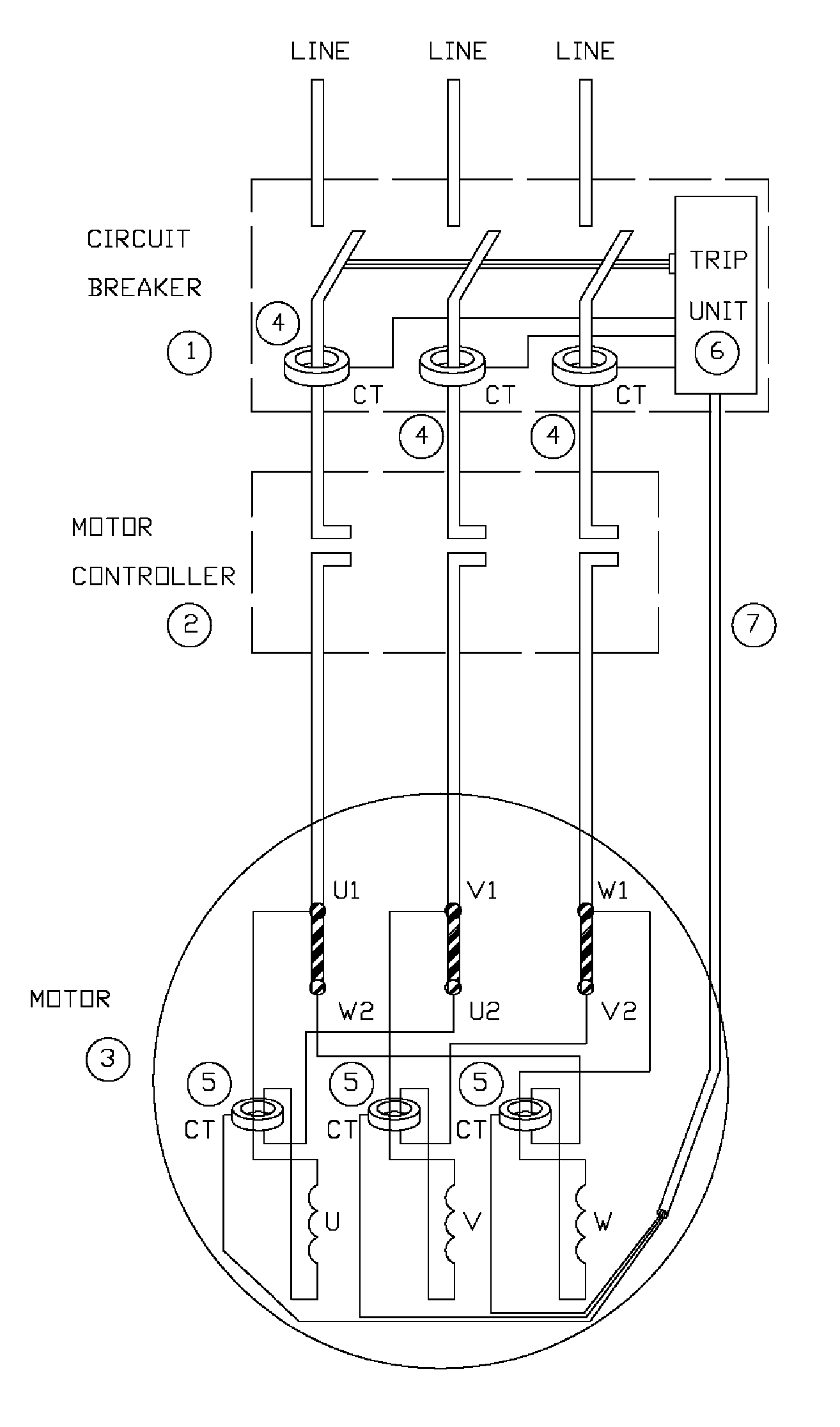
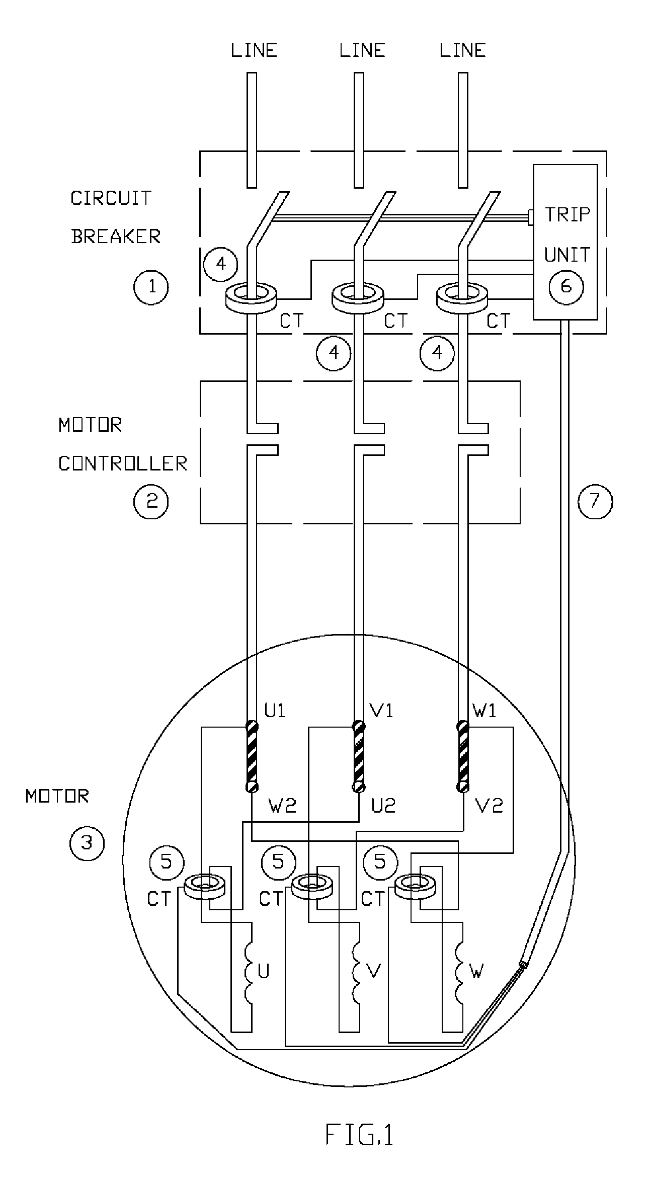
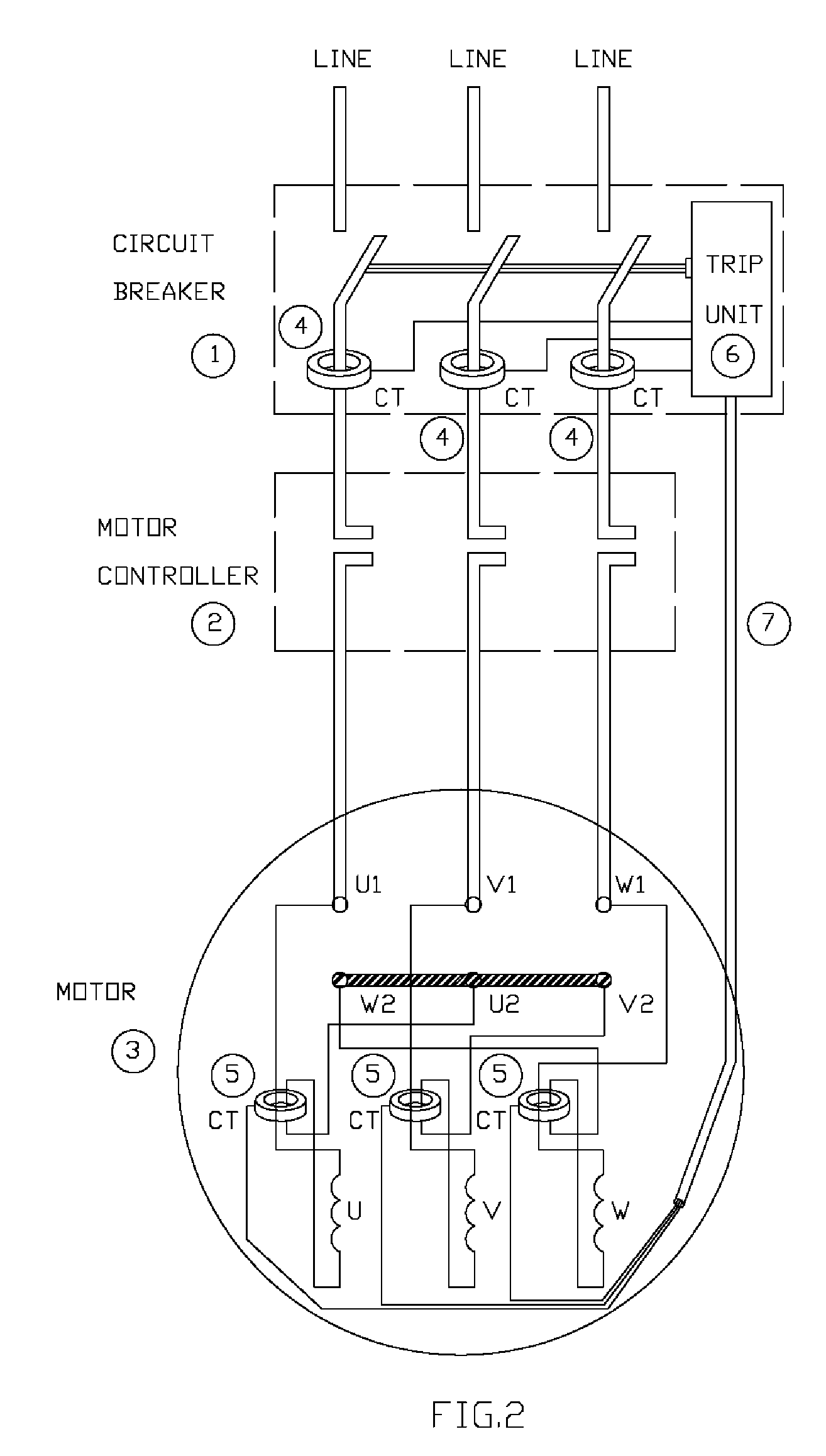
[0017] Referring to the drawings; FIG. 1 and FIG. 2 show the typical view of the possible embodiment of the present invention with a motor load. A circuit breaker 1 is a supply circuit breaker for a motor 3. A motor controller contactor 2 is closed when motor 3 in operating. The important parts of circuit breaker 1 are current transformers 4 and a trip unit 6.

[0018] Trip unit 6 is connected to current transformers 4 which are part of circuit breaker 1 and measure the currents in the supply feeder (line) and to the current transformers 5 which form a part of the protection for motor 3 and measure currents in the motor phases. Current transformers can be replaced with any form of suitable current transducers. Trip unit 6 evaluates a rate-of-change of current in the supply feeder and produces a differential signal proportional to a difference between a current in the supply feeder and the current in the motor. To obtain a true differential signal, the connections of the current transf...


PUM


Abstract

A two channel universal device for advanced protection from a short circuit current which evaluates a rate-of-change of current in a supply feeder and compares the current in the supply feeder and the current in load phases generating a differential signal in such a way that in normal conditions, when the load is running or starting, the differential signal is virtually zero. The differential signal and the rate-of-change of current in the supply feeder are compared with the settings of the protective device. If both the value of the rate-of-change of current and the value of the differential signal simultaneously exceed their settings, after an adjustable time delay, the device produces a signal to open the circuit. The existence of two conditions necessary to initiate the trip signal to cause the circuit to open ensures the reliable operation of this device and provides a feasible fast protection scheme.

Description

CROSS-REFERENCE [0001] Latest protection arrangements in this field are shown in the following United States of America patents: 5,181,155Jan. 19, 1993Beg et al.6,061,217May 09, 2000Grunert et al.6,373,014Apr. 16, 2002Mitsuhashi et al.6,633,474Oct. 14, 2003Boudaud6,873,236Mar. 29, 2005Shah et al.BACKGROUND OF THE INVENTION [0002] The invention is generally associated with fault detection and circuit protection devices (circuit breakers) in AC power electrical systems. It could also be used in DC power electrical protection systems. [0003] Circuit breakers are used to protect electrical circuits from a short circuit current and overloads. These devices in conjunction with the fault detection relay, in general, are designed to sense the existence of the fault current in the protected circuit and then to disconnect the faulty circuit from the source of power. In some devices the trip operation setting (the level of the current which leads to the operation of the protective device) can...

Claims


Application Information

Patent Timeline
IPC IPC(8): H02H9/08
CPCH01H83/14H02H7/26H02H3/44H02H3/093
Inventor ROZINE, VASSILIADAMS, MAX H.
Owner ROZINE VASSILI
Why Eureka
Try Eureka