Injector

a technology of injectors and needles, applied in the field of injectors, can solve the problems of difficult to figure out the location of the loop b, difficult to handle the forceps, and large dependence on surgery, and achieve the effect of easy to figure out the direction

Inactive Publication Date: 2006-12-28
HOYA CORP
View PDF8 Cites 65 Cited by
  • Summary
  • Abstract
  • Description
  • Claims
  • Application Information

AI Technical Summary

Benefits of technology

[0011] Accordingly, as it is possible to easily figure out the orientation of the intraocular lens loaded in the cartridge at the time the intraocular lens is inserted, a cornea or the like can be prevented from being harmed by the loop of the intraocular lens.
[0013] Accordingly, as it is possible to easily figure out the orientation of the intraocular lens loaded in the cartridge at the time the intraocular lens is inserted, a cornea or the like can be prevented from being harmed by the loop of the intraocular lens.
[0015] Accordingly, as it is possible to easily figure out the orientation of the intraocular lens loaded in the cartridge at the time the intraocular lens is inserted, a cornea or the like can be prevented from being harmed by the loop of the intraocular lens.
[0017] Accordingly, also in the injector which folds the intraocular lens front side out and rotates the lens in the same direction as that in the case of using a forceps, it is possible to easily figure out an angle at which the ejection-side loop of the intraocular lens loaded in the cartridge becomes in parallel to the surface of the eye. It is also possible to easily figure out the direction of rotating the cartridge when the intraocular lens is ejected into the eye, thus preventing the inserted intraocular lens from turning upside down.
[0019] This makes it possible to easily figure out the direction of the rotation and the amount of the rotation, so that the inserted intraocular lens does not turn upside down.

Problems solved by technology

According to the method, however, handling the forceps is difficult, and there are risks such as dropping the intraocular lens 7 and enlarging the incision, which brings about a problem such that the surgery largely depends on the skill of the operator.
Since the loop 72 is very small, however, there is a problem such that it is difficult to figure out a location where the loop 72 becomes parallel.
As this rotation direction is opposite to the direction in the case where the forceps is used, however, there is a problem such that the operator is liable to mishandle the work.
Even in this case, however, there are problems such that the operator would wonder in which direction the injector should be rotated, and would have a difficulty in determining how much it should be rotated.

Method used


Image

  • Injector
  • Injector
  • Injector

Examples


first embodiment

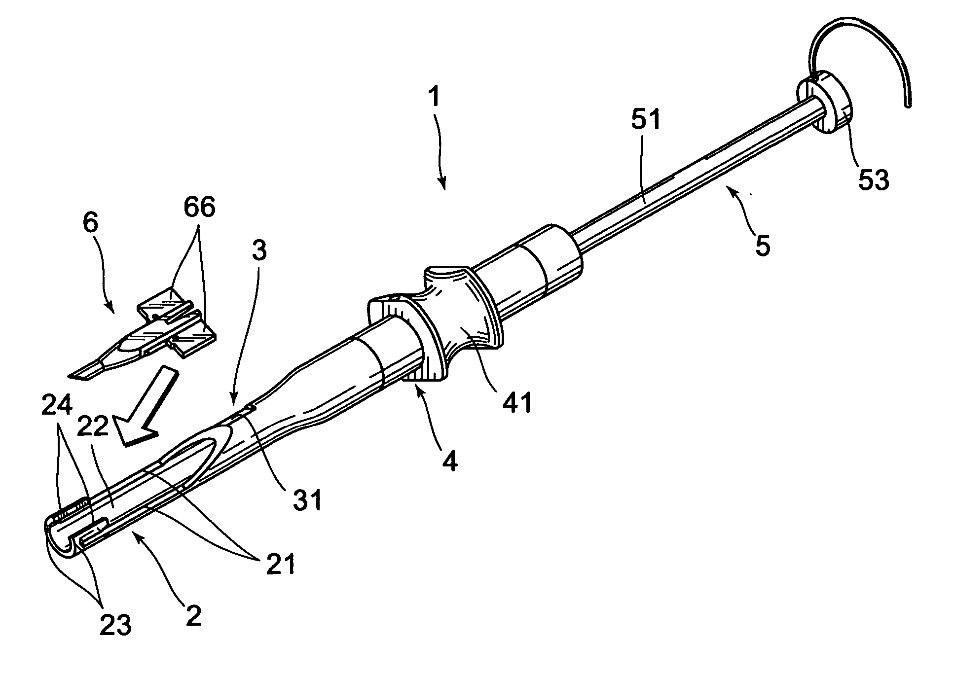
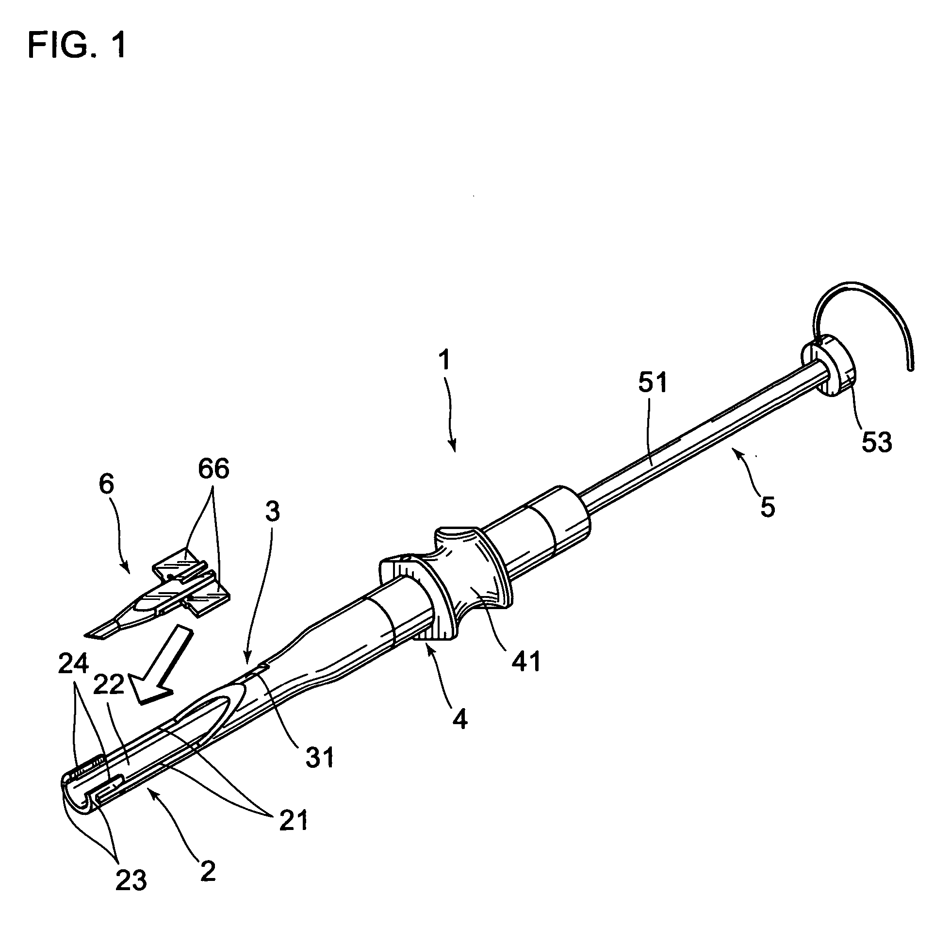
[0028] the invention is an injector provided with insertion-start-position indicating means.

[0029] As illustrated in FIG. 1, an injector 1 comprises an injector main body 4 having insertion-complete-position indicating means 2 on which a cartridge 6 is detachably mounted, and which indicates a position as a measure of completing insertion of an intraocular lens and insertion-start-position indicating means 3 which indicates a position as a measure of starting the insertion of the intraocular lens 7, and ejection means 5 which can eject the intraocular lens 7, loaded in the cartridge 6, out of the cartridge 6. Various materials can be used for the injector 1 unless they cause a trouble in the insertion of the intraocular lens 7 into an eye; for example, metals, such as stainless steel and titanium, can be used.

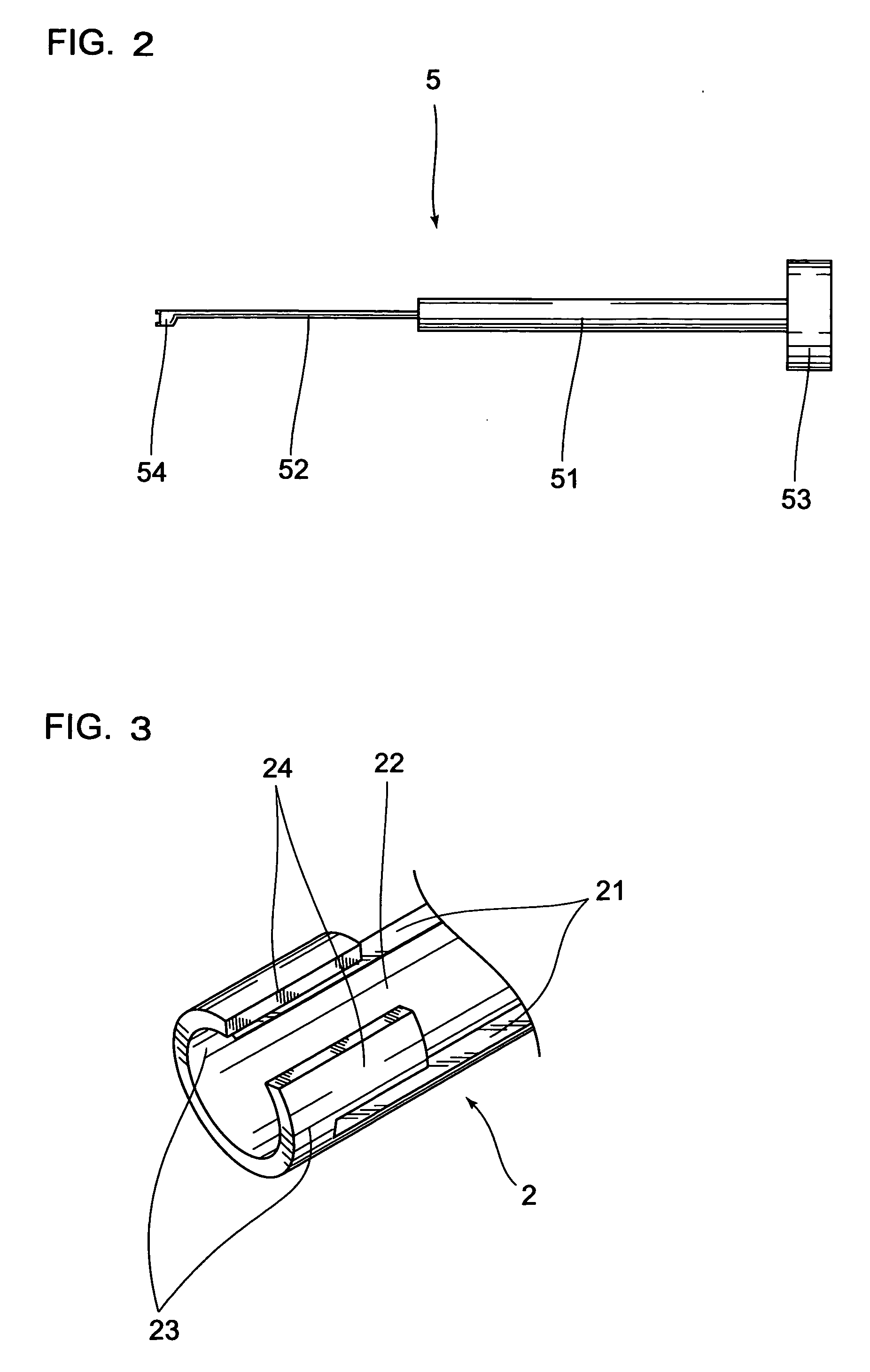
[0030] As illustrated in FIG. 2, the ejection means 5 comprises a base 51 which is fitted into the injector main body 4, a pushrod 52 which is formed on one end side of the ba...

second embodiment

[0043] the invention is an injector provided with rotation-direction indicating means.

[0044] As illustrated in FIG. 6, insertion-start-position indicating means 32 is formed in a hemi-arcuate shape in cross section by cutting the injector main body 4 in half at an arbitrary width, and is formed in such a way that the loop 72 on the ejection side becomes parallel to the surface of an eye when two insertion-position indication portions 33 are arranged in parallel to the surface of the eye.

[0045] Rotation-direction indicating means 9 is so formed in a hemi-arcuate shape in cross section as to have a rotation-direction indication channels 91 which connect the insertion-position indication portions 33 of the insertion-start-position indicating means 32 to the guide channels 21 of the insertion-complete-position indicating means 2, and is so formed as to turn the insertion-complete-position indicating means 2 counterclockwise from the insertion-start-position indicating means 32 with res...


PUM


Abstract

An injector which enables an operator to safely insert an intraocular lens without a mishandling is provided. An injector 1 for inserting an intraocular lens which has a loop folded and loaded in a cartridge into an eye by pushing out that lens while rotating it, comprises insertion-start-position indicating means 32 which indicates a position at the time of starting inserting the intraocular lens, and insertion-complete-position indicating means 2 which indicates a position at the time of completing the insertion of the intraocular lens. It is possible to easily figure out the orientation of the intraocular lens loaded in the cartridge 6 at the time of inserting the intraocular lens, thus making it possible to prevent a cornea or the like from being harmed by the loop of the intraocular lens.

Description

TECHNICAL FIELD [0001] The present invention relates to an injector which is used at the time of inserting an intraocular lens into a capsula lentis. BACKGROUND ART [0002] There is a method of implanting an intraocular lens 7 which has, as illustrated in FIG. 7, an optical part 71, and two loops 72 and 73 provided on opposing portions of the optical part 71 and supporting the optical part 71 from an incision formed in an eyeball instead of a crystalline lens which has lost its function due to cataract, thereby recovering a vision (see, for example, Patent Literature 1). [0003] From the standpoint of hastening the recovery of a patient, it is desired that the incision is as small as possible. Because of this demand, a soft material, such as a silicon resin, an acrylate resin, or a hydrogel, is recently used as the material of the intraocular lens 7, and a surgery of inserting the intraocular lens from a small incision with that lens rolled or folded is performed. [0004] As the method...

Claims


Application Information

Patent Timeline
Patent Type & Authority Applications(United States)
IPC IPC(8): A61F9/00A61F2/16
CPCA61F2/1678A61F2/167
Inventor FUTAMURA, HIDEYUKI
Owner HOYA CORP
Why Eureka
Try Eureka