Non-contact laser carving process and the equipment

a laser carving and non-contact technology, applied in the direction of manufacturing tools, solid-state devices, semiconductor/solid-state device details, etc., can solve the problems of ineffective control of the quality of the carved characters, the shape, size and depth of the carved characters cannot be uniform, and the wafer breaks, so as to achieve efficient trace and control, reduce the amount and improve the quality of the carved character

Inactive Publication Date: 2008-10-30
LITE ON SEMICON
View PDF0 Cites 1 Cited by
  • Summary
  • Abstract
  • Description
  • Claims
  • Application Information

AI Technical Summary

Benefits of technology

[0016]An object of the present invention is to provide a non-contact laser carving process and the equipment, which makes use of the orientation of an orienting module to precisely amend and orient the center of a wafer to the orienting module so that the wafer won't contact or collide with other objects to cause any crack on the flat corner surface or any breakage of wafer. Besides, the present invention makes use of the rotation of the orienting module and an optical sensor of a transmission mechanical module to precisely get the center of the wafer, and also makes use of the compensation of the optical sensor to orient a specific boundary position.
[0017]No matter what the external diameter of the wafer is, laser carving can be precisely performed at the specific boundary position in the wafer by the compensation and transmission of the transmission mechanical module cooperated with the laser-carving unit, and a specific number can be carved at the specific boundary position of each wafer. Therefore, the wafer can be efficiently traced and controlled, and the amount of the wafer can be figured out easily to raise the quality of the wafer when the wafer is produced and transported.
[0018]To achieve the above object, the present invention provides a non-contact laser carving process, which is used to carve a specific number on each wafer by laser so as to efficiently trace and control wafers and easily figure out the amount of wafers. The process comprises the steps of: using an entry station unit to load and transport a wafer; using an orienting unit to fetch the wafer loaded and delivered by the entry station unit and to amend and orient the center of the wafer; using a transmission unit cooperated with the orienting unit to perform edge-detecting orientation and boundary position compensation of the wafer and to receive the wafer for transmission; using a laser carving unit cooperated with the transmission unit to carve a specific number at a predetermined boundary position of the wafer by laser; and using an exit station unit cooperated with the transmission unit to unload and transport the wafer with the specific number.
[0019]To achieve the above object, the present invention also provides a non-contact laser carving equipment, which is used to carve a specific number on each wafer by laser so as to efficiently trace and control wafers and easily figure out the amount of wafers. The equipment comprises an entry station unit and an exit station unit, an orienting unit corresponding to the entry station unit, a transmission unit, and a laser carving unit. The entry station unit and the exit station unit have an entry deliver region and an exit deliver region for entry and exit loading and transport of each wafer, respectively. The orienting unit is used to fetch the wafer loaded by the entry station unit and to amend and orient the center of the wafer. The transmission unit cooperates with the orienting unit to perform edge-detecting orientation, boundary position compensation and transmission of each wafer. The laser carving unit cooperates with the transmission unit to carve a specific number at a predetermined boundary position of a wafer by laser so as to let each wafer have a specific number.

Problems solved by technology

Because the above conventional manual wafer carving manner depends on the strength of each operator, it has the following drawbacks:(1) Because the applied strength is generally inconsistent, the shape, size, and depth of the carved characters cannot be made uniform.
Therefore, the quality of the carved characters cannot be effectively controlled.(2) Too large applied strengths limit the number of characters that are carved on the wafer, and may even cause breakage of the wafer.(3) Because of the difference in the sanitary habit, the cleanness degree of the wafer accessed by each operator differs, and the possibility of potential contamination and crack of the wafer during carving may exist.(4) Because the operator needs to directly access the wafer, the cleanness degree and crack on the wafer and the applied strength cannot be effectively controlled.
Because of the hardness of the wafer, there will be scars formed on the orienting stopper to cause the following disadvantages:(1) Owing to the scars, the deviation of the wafer during the center orientation will happen, resulting in the deviation of the position of the carved characters.
Therefore, the laser carving action cannot be precisely carried out on the position of the carved characters.(2) Owing to the non-uniformity of the scars, crack on the flat corner surface of the wafer may easily occur, not only causing the breakage of the wafer, but also affecting the integrity of the whole wafer.

Method used


Image

  • Non-contact laser carving process and the equipment
  • Non-contact laser carving process and the equipment
  • Non-contact laser carving process and the equipment

Examples


Embodiment Construction

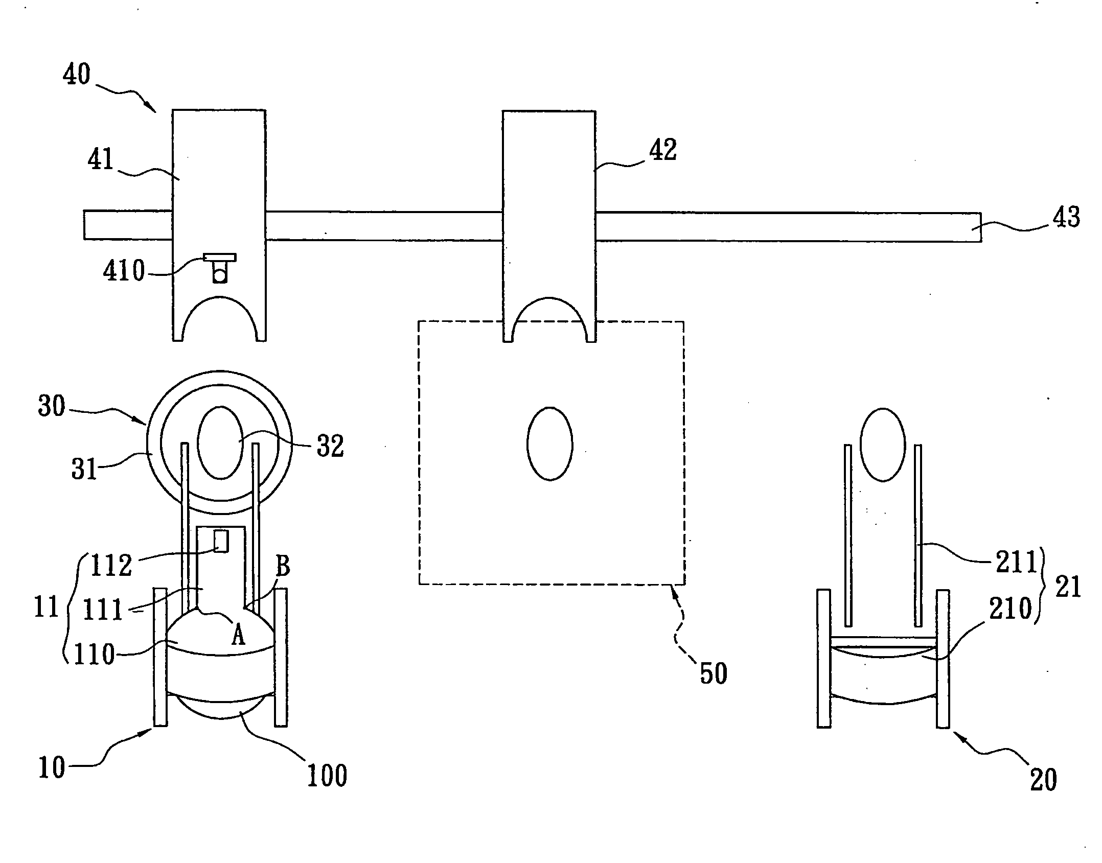
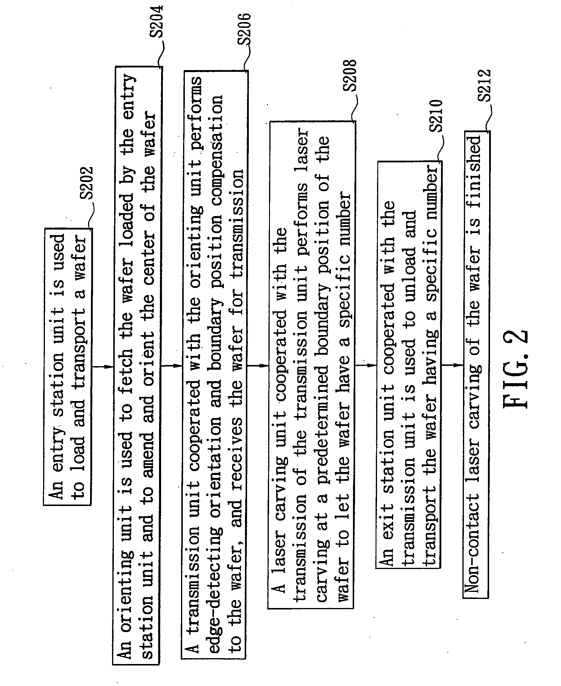
[0038]As shown in FIGS. 2 and 3, the present invention provides a non-contact laser carving process and the equipment, which are used to carve a specific number on each wafer 100 by laser so as to efficiently trace and control each wafer 100 and easily figure out the amount of wafer. The non-contact laser carving process comprises the following steps. First, an entry station unit 10 is used to load and transport a wafer 100 (Step S202). An orienting unit 30 is then used to fetch the wafer 100 loaded by the entry station unit 10 and to amend and orient the center of the wafer 100 (Step S204). Next, a transmission unit 40 cooperated with the orienting unit 30 performs edge-detecting orientation and boundary position compensation to the wafer 100, and receives the wafer 100 for transmission (Step S206). Subsequently, a laser carving unit 50 cooperated with the transmission of the transmission unit 40 performs laser carving at a predetermined boundary position of the wafer 100 to let th...


PUM

PropertyMeasurementUnit
sizeaaaaaaaaaa
transmissionaaaaaaaaaa
transmission mechanismaaaaaaaaaa

Abstract

A non-contact laser carving process and the equipment. By the orientation of an orienting module, the center of a wafer can be amended and oriented to the orienting module precisely. By the rotation of the orienting module and an optical sensor of a transmission mechanical module, the center of the wafer can be obtained precisely. By the compensation of the optical sensor, a specific boundary position is oriented. No matter what the external diameter of the wafer is, the specific boundary position in the wafer can be carved by laser precisely through the transmission mechanical module cooperated with a laser-carving unit, and a specific number can be carved at the specific boundary position of each wafer. Therefore, the wafer can be efficiently traced and controlled, and the amount of the wafer can be figured out easily to raise the quality of the wafer.

Description

BACKGROUND OF THE INVENTION[0001]1. Field of the invention[0002]The present invention relates to a non-contact laser carving process and the equipment, more particularly, to a non-contact laser carving process and the equipment, which makes use of an orienting module cooperated with a transmission mechanical module to accomplish edge detection and detection compensation so as to obtain a predetermined position on a wafer and allow a laser carving unit to carve a specific number at the predetermined position.[0003]2. Description of Related Art[0004]In modernized society that changes with each passing day, various high-tech products used in information and communications have become more and more complicated, and various electronic and mechanical components used in these high-tech products have become the driving power for diversified functions of these high-tech products. Among most electronic or automated products, control chips are used as the most important core components for the...

Claims


Application Information

Patent Timeline
Patent Type & Authority Applications(United States)
IPC IPC(8): B23K26/00
CPCB23K26/02H01L21/681H01L23/544H01L2223/54406H01L2223/54433H01L2223/54453B23K26/041B23K26/026B23K26/035B23K26/042H01L2924/0002
Inventor HUANG, TSUNG-CHIENTIEN, CHIU-HUNGLEE, HSUN-MIN
Owner LITE ON SEMICON
Why Eureka
Try Eureka