Strapless prosthetic arm

a prosthetic arm and strapless technology, applied in the field of prosthetics, can solve the problems of chafing against the patient's body giving rise to sores and abrasions, unable to independently support the weight of the lower limb prosthesis, and unable to achieve the effect of securing the strap,

Active Publication Date: 2006-12-28
ALFRED E MANN FOUND FOR SCI RES
View PDF5 Cites 72 Cited by
  • Summary
  • Abstract
  • Description
  • Claims
  • Application Information

AI Technical Summary

Problems solved by technology

Gravitational and other forces tend to cause separation between the prosthetic limb and the patient's residual extremity during use.
Such devices are inconvenient and can cause chafing against the patient's body giving rise to sores and abrasions.
Though the principle of employing “suction” for “suspending” an artificial limb is clear, there are practical problems.
One of these is the difficulty in providing a reliable and permanently effective seal at the proximal open end of the socket, this issue is important in maintaining the reduced pressure inside the socket.
In some instances it is doubtful whether the suspending suctional force can independently support the weight of the lower limb prosthesis.
This is problematic from a safety stand-point, because if the suspension fails, and there is no redundant or back-up support mechanism, the artificial limb could detach from the patient's stump.
U.S. Pat. No. 5,376,131 to Lenze, et al. discloses a socket with an elastic diaphragm that engages a patient's stump, and attempts to provide an effective seal, but the local constriction due to such a tight fitting diaphragm can result in impairment of circulation in the amputee's residual limb.
Since these sleeves constrictingly grip the residual limb over a wide region they can limit limb movement or be uncomfortable.
Though this may be advantageous, it can make it difficult for the patient to consistently achieve the same prosthetic configuration when the residual limb and the artificial limb are articulated.
But, this can be misleading because the suction socket may not be sealingly gripped by the hard socket, thereby converting the suction socket to a “traction” socket.
This skin traction causes an undesirable “tethering” effect by pulling on the skin, thereby creating multiple skin problems.
The length of the tube can also interfere with the mobility of the residual limb, especially in the case of below-knee amputees.
Such an alignment mechanism can be hazardous.
During use of the prosthesis the interface between the socket and the artificial limb is subjected to stresses and moments that can result in relative motion between the alignment plates, thus misaligning the prosthesis.
In extreme cases, the coupling plates may become unfastened, thereby, placing the patient at risk.
The conventional alignment device adds excess weight to the prosthesis as well as adding to the cost, since it is a complicated device which is fabricated from titanium.
Also, the size of the alignment device undesirably adds to the overall length of the prosthesis, which can be problematic when accommodating long stump lengths.
Despite the large number of suspension options available, none act to eliminate rotation between the hard socket and the suction liner.
This is not comfortable for the limb.
Therefore, there has been a trend toward more naturally-shaped sockets, making rotation control even more difficult.

Method used


Image

  • Strapless prosthetic arm
  • Strapless prosthetic arm
  • Strapless prosthetic arm

Examples


Embodiment Construction

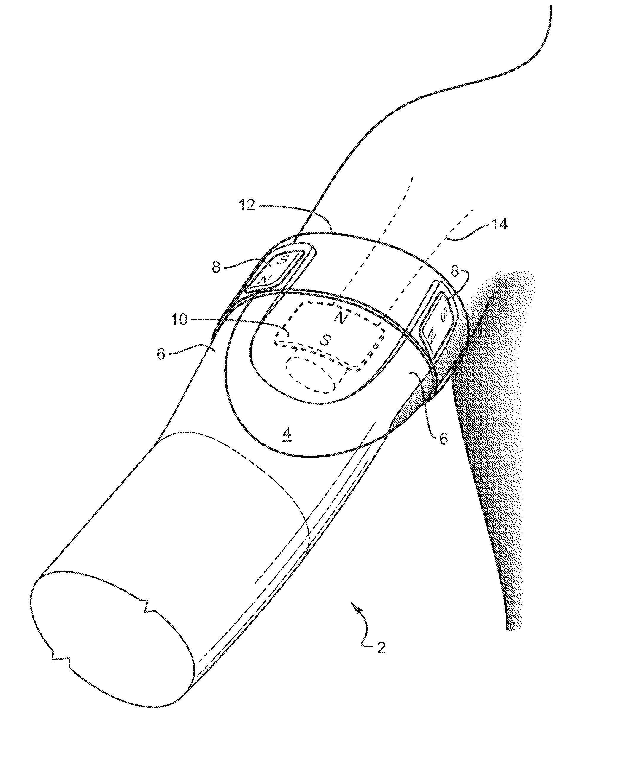
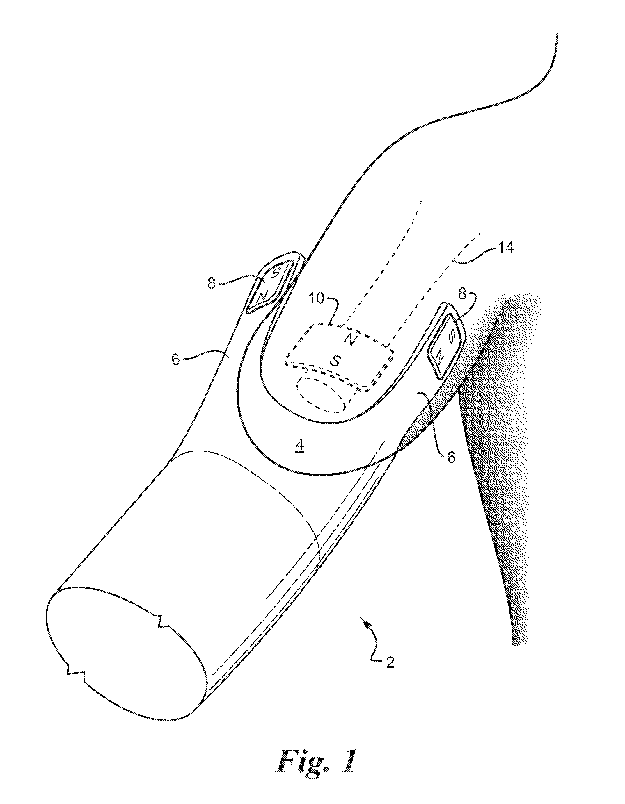
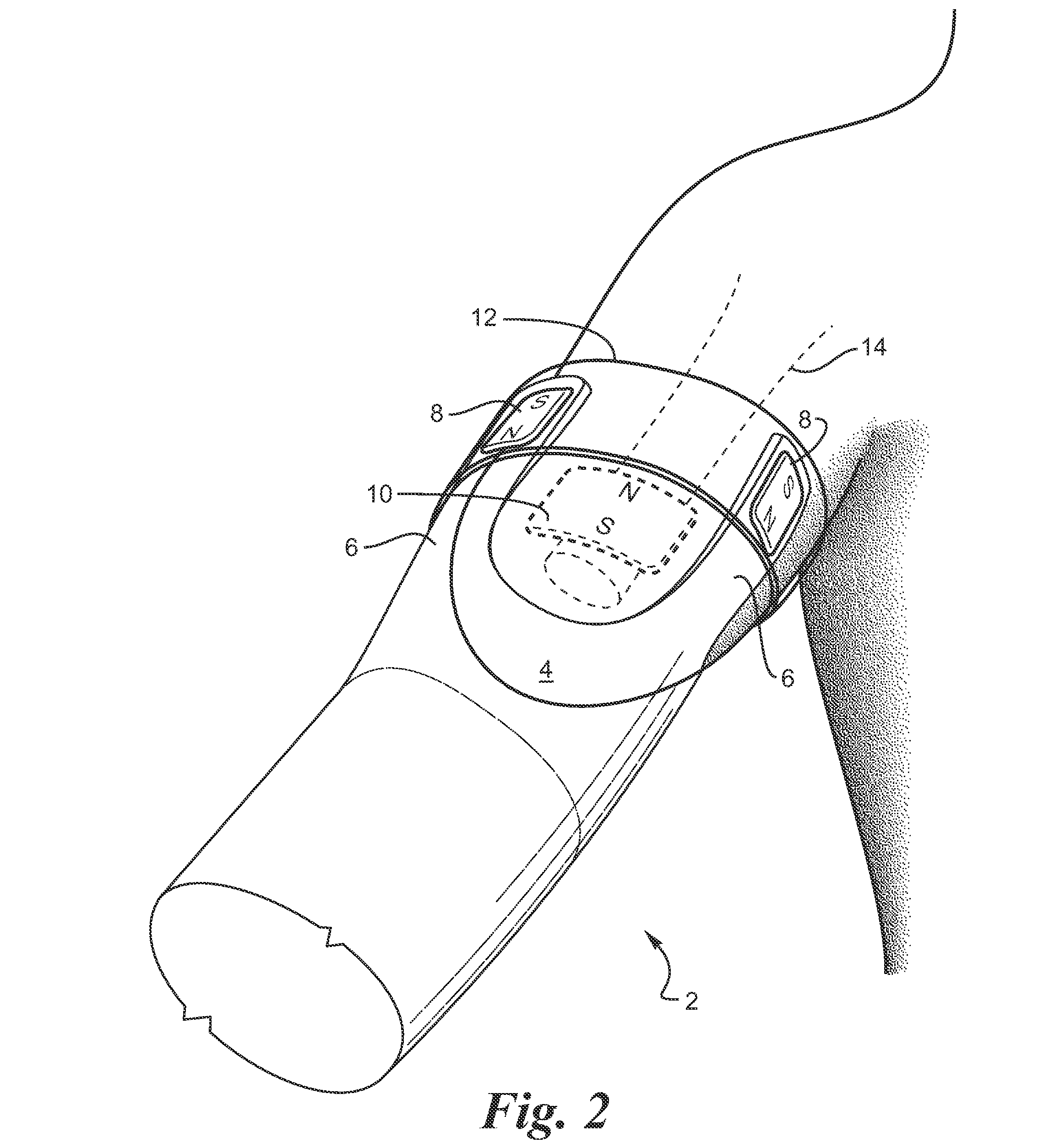
[0022]FIG. 1 provides a perspective view of a preferred embodiment of an arm extremity 4 with internal bone 14 and prosthesis 2. A magnet 10 is implanted in the extremity 4 to facilitate in retaining the prosthesis 2 on the extremity 4 by the magnetic repelling force generated by similar magnetic poles being placed facing each other of implanted magnet 10 and attachment magnets 8 that are securedly fastened in an attachment flap 6 of the prosthesis 2. In the illustration, the north poles of the implanted magnet 10 and of the attachment magnet 8 are repelling each other thereby urging the prosthesis 2 into retention on the extremity 4. Attachment flap 6 may be comprised of a rigid non-magnet rigid material such as a plastic or a flexible material such as a cloth.

[0023] The embodiment presented in FIG. 1 illustrates one implanted magnet 10, although it is preferable to have a plurality of implanted magnets 10 disposed at intervals around the extremity 4 to facilitate creation of an e...


PUM


Abstract

Permanent magnets or electromagnets or a combination of such magnets are provided to retain a prosthetic device on an extremity, such as an arm. The prosthesis utilizes the opposing forces, which are developed by virtue of like magnetic poles being in proximity to each other, to urge the prosthesis to remain attached to the extremity. The prosthesis is prevented from rotation by virtue of a centering force that is provided by an attachment magnet in the prosthesis being placed between two implanted magnets. A removable mounting ring is placed over the prosthesis straps to maintain them in proximity to the extremity.

Description

CROSS REFERENCE TO RELATED APPLICATION [0001] This application claims the benefit of U.S. Provisional Application Ser. No. 60-694,012, filed on Jun. 25, 2005.FIELD OF THE INVENTION [0002] The present invention relates generally to prosthetics, and, more specifically to an attachment system used in the donning / doffing and use of a socket on a residual limb. The present invention more particularly relates to an attachment system that utilizes magnets for mounting to the limb and that controls rotation of the mounted prosthesis. BACKGROUND OF THE INVENTION [0003] It has long been appreciated that differential air pressure or “suction” may be utilized to retain or “suspend” a prosthetic limb on an amputee's stump. Gravitational and other forces tend to cause separation between the prosthetic limb and the patient's residual extremity during use. This happens, for example, during the swing phase of gait, when a prosthetic leg is additionally subjected to centrifugal forces. Patients have ...

Claims


Application Information

Patent Timeline
Patent Type & Authority Applications(United States)
IPC IPC(8): A61F2/78
CPCA61F2/78A61F2210/009A61F2002/546
Inventor SCHULMAN, JOSEPH H.BYERS, CHARLES L.
Owner ALFRED E MANN FOUND FOR SCI RES
Why Eureka
Try Eureka