Method and a device for removing vehicle windows

a vehicle and window technology, applied in the direction of sawing components, transportation and packaging, sawing apparatus, etc., can solve the problems of reducing the service life of the vehicle, the apparent risk of damaging both the actual window element and the interior or exterior parts of the vehicle, and the cleaning and additional cost of a new window element, so as to achieve secure and effective non-destructive

Inactive Publication Date: 2007-01-04
RAMHUSET DALA SPEGLAR
View PDF10 Cites 28 Cited by
  • Summary
  • Abstract
  • Description
  • Claims
  • Application Information

AI Technical Summary

Benefits of technology

[0009] Briefly, the invention provides a method for removing very small fixed vehicle side windows using a cutting wire that is threaded through the window element adhesive, that is placed in a loop around the perimeter of the window element and that is forced to cut through the adhesive around the entire window element by being pulled by means of wire wind-up means of a window element removal device that is fixed relative to the window. According to the invention said device is fitted to a window element frame, is expanded into firm clamping engagement with the window element frame and is locked in said position firmly engaging the window element frame. The wire wind-up means are then operated until the wire cuts through the adhesive at the edge of the side window element around the entire perimeter thereof. The suggested method permits the use of a very compact device, both with regard to the actual space occupied thereby a

Problems solved by technology

All of the described methods are comparatively time-consuming and cumbersome and involve an apparent risk of damaging both the actual window element and interior or exterior parts of the vehicle.
In such situations, it has up to the present day been common practice to crush the window element, with the resulting cleaning and additional cost of a new window element.
The only remaining options are to use one of the above described time-consuming, cumber

Method used


Image

  • Method and a device for removing vehicle windows
  • Method and a device for removing vehicle windows
  • Method and a device for removing vehicle windows

Examples


Embodiment Construction

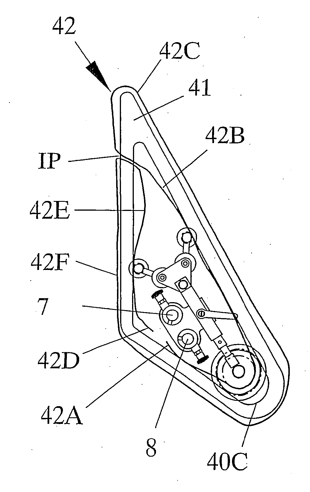
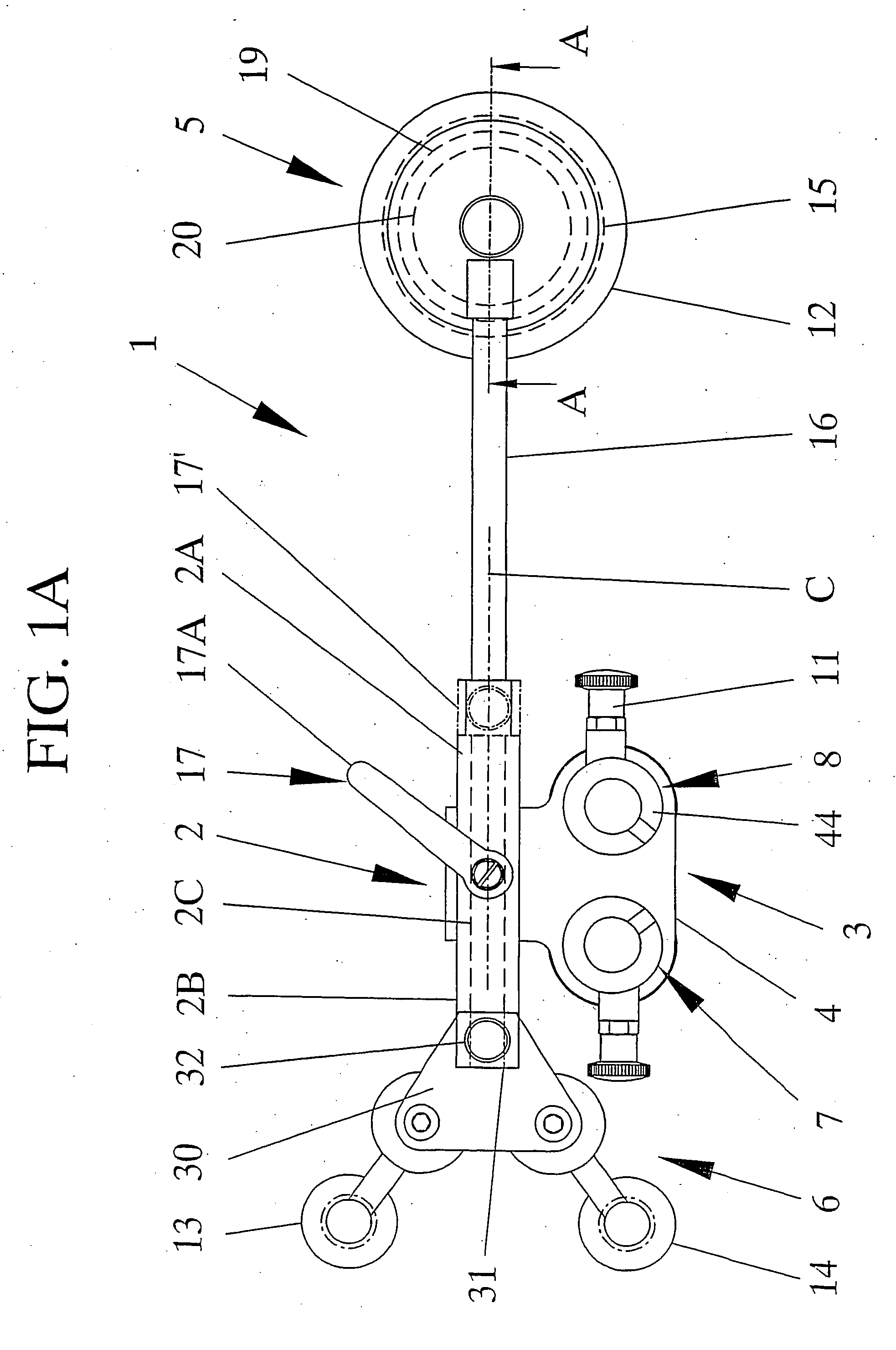
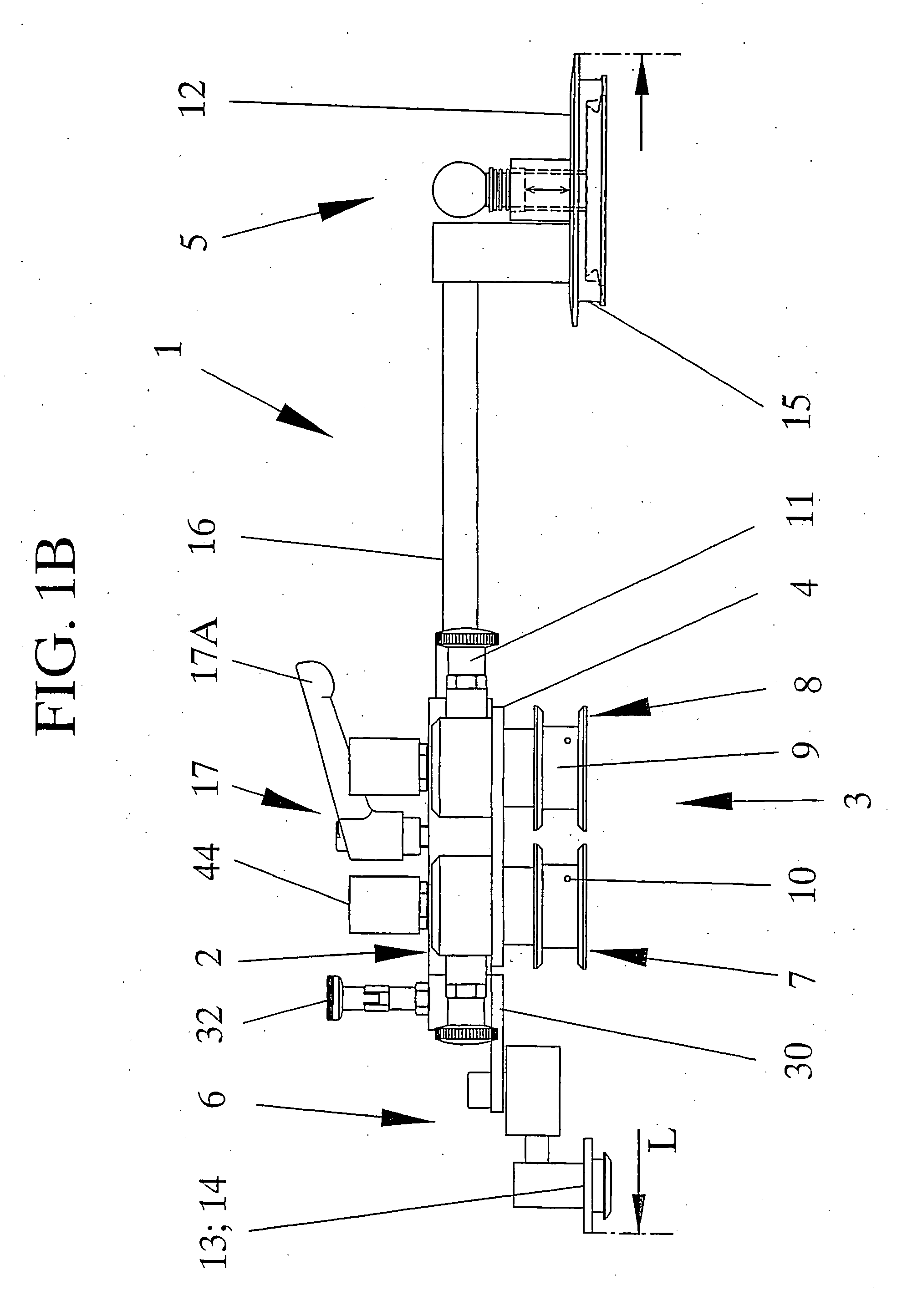
[0026] An exemplary illustrative embodiment of the device or tool 1 according to the invention is illustrated in FIGS. 1A-B, 2A-B and 3A-3B. The basic design of this tool 1 is based on that of a hand tool that is presently used in the inventors own system “Roll out 2000®” for cutting the sealant / adhesive bonding a vehicle windshield to the vehicle body and thus for removing such a windshield. In said basic design, the tool 1 has an elongate handle 2 connected to a wire wind-up means 3 and first and second tool attachment means 5,6 that are supported by each end section 2A, 2B of the handle 2.

[0027] In contrast to the above mentioned, known tool the wire wind-up means 3 of the tool 1 of the present invention is preferably provided with two winch mechanisms 7,8. Said winch mechanisms 7,8 are supported on a bracket 4 that is attached to the tool 1, generally at a mid-portion of the handle 2. In this embodiment the pair of winch mechanisms 7,8 are provided side by side, at a distance f...


PUM

PropertyMeasurementUnit
Timeaaaaaaaaaa
Electric chargeaaaaaaaaaa
Currentaaaaaaaaaa

Abstract

A method for the non-destructive removal of very small fixed window elements (40) from vehicles uses a cutting wire that is threaded through the adhesive bonding a window element to a vehicle, that is placed in a loop around the perimeter of the window element and that is pulled by wire wind-up elements (3) of a window element removal device. The device (1) is fitted to a window element frame (41), is expanded into firm clamping engagement with the window element frame (41) and is locked in the position firmly engaging the window element frame (41). The wire wind-up elements (3) are then operated until the wire cuts through the adhesive at the edge of the side window element around the entire perimeter thereof.

Description

TECHNICAL FIELD [0001] The present invention relates in general to fixed window elements of vehicles. In particular, the invention relates to a method and a device for removing a fixed side window from a vehicle. BACKGROUND OF THE INVENTION [0002] The removal of fixed vehicle glazing in one piece for replacement or salvage purposes involves penetrating and cutting through the adhesive seal bonding a window element to an associated frame of a vehicle. Throughout the years, various methods for the removal of mainly vehicle windshields and rear windows have been suggested and practiced. Among such known methods are those where a knife or similar tool is used to cut through the adhesive bond and an outward pressure is simultaneously applied to the windshield, see e.g. U.S. Pat. No. 6,101,702. Other methods make use of a wire that is threaded through the adhesive bond and that is moved back and forth to cut through the seal all around the perimeter of the windshield, see e.g. U.S. Pat. N...

Claims


Application Information

Patent Timeline
IPC IPC(8): B26D1/00B26D1/48B25B11/00B26B27/00B26D1/547B62D65/08
CPCB25B11/007B26B27/002Y10S269/909Y10T29/49821Y10T29/49998B26D1/547B62D67/00Y02W30/56Y10T83/424Y10T83/04Y10T83/929
Inventor ERICSON, ROLF
Owner RAMHUSET DALA SPEGLAR
Why Eureka
Try Eureka