Roller blind with electronic pinch protection

a technology of electronic pinch protection and roller blinds, which is applied in the field of windscreen shades, can solve the problems of reducing the risk of pulling rod pinching an obstacle during operation, and reducing the risk of injury through pinching

Inactive Publication Date: 2007-01-04
BOS
View PDF19 Cites 6 Cited by
  • Summary
  • Abstract
  • Description
  • Claims
  • Application Information

AI Technical Summary

Benefits of technology

[0006] It is an object of the invention to provide a roller blind for motor vehicles that is safe to operate and in which the risk of injury through pinching is reduced.

Problems solved by technology

Due to the electromotor drive mechanism, there is a certain risk of the pull rod pinching an obstacle during operation.
The operating force is comparatively high and there is a risk of injury if someone were to reach between the moving pull rod and a fixed buffer in the vehicle.
Such danger exists in the course of both retraction and extension of the shade.
The danger particularly exists for side windows when the side window is lowered.
In rear windows wherein the window shade pull-out is operated via a lever arrangement, a danger of pinching also arises when the shade is retracted because the pull-out power is not passive via the spring motor of the winding shaft but is operated via the electromotor.

Method used


Image

  • Roller blind with electronic pinch protection
  • Roller blind with electronic pinch protection
  • Roller blind with electronic pinch protection

Examples


Embodiment Construction

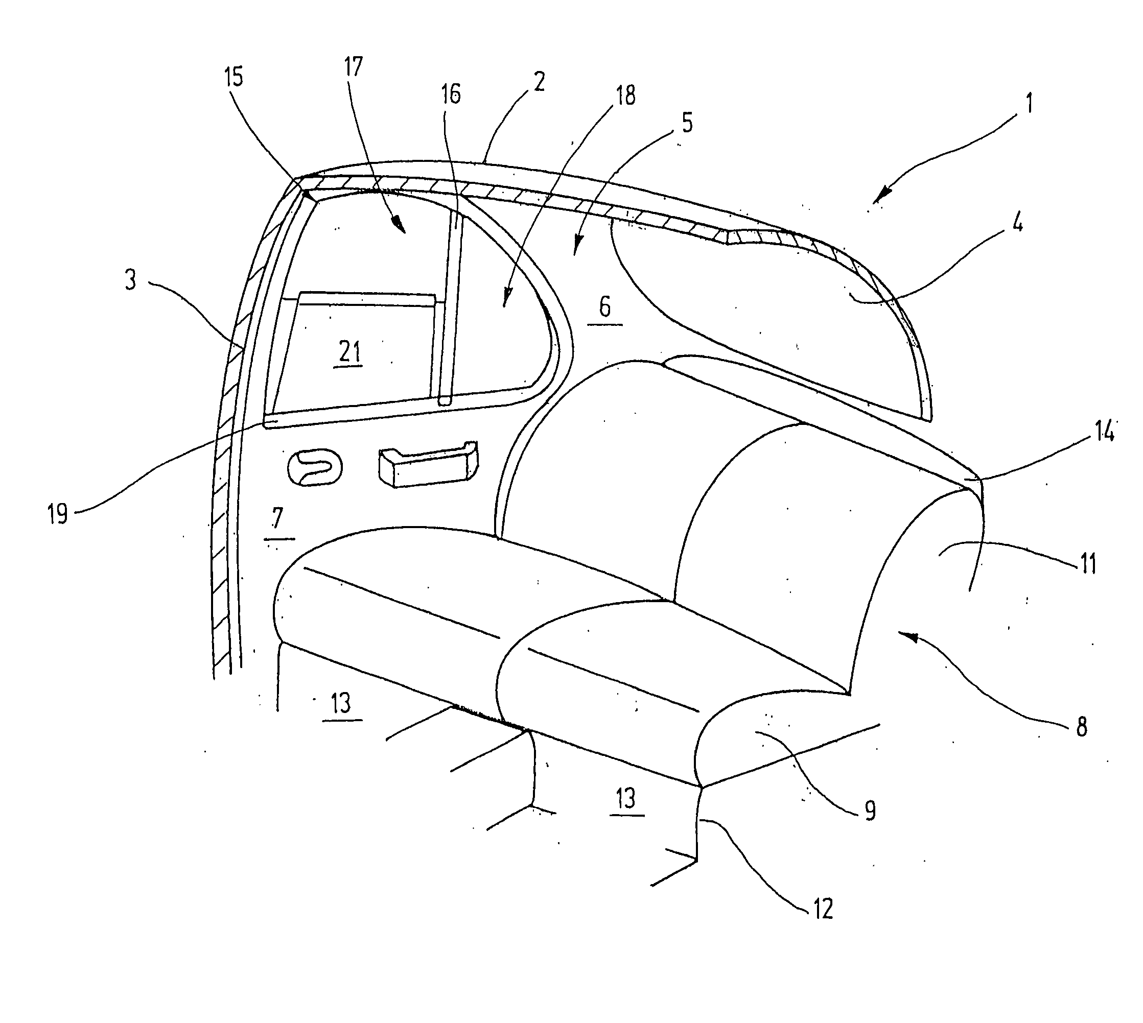
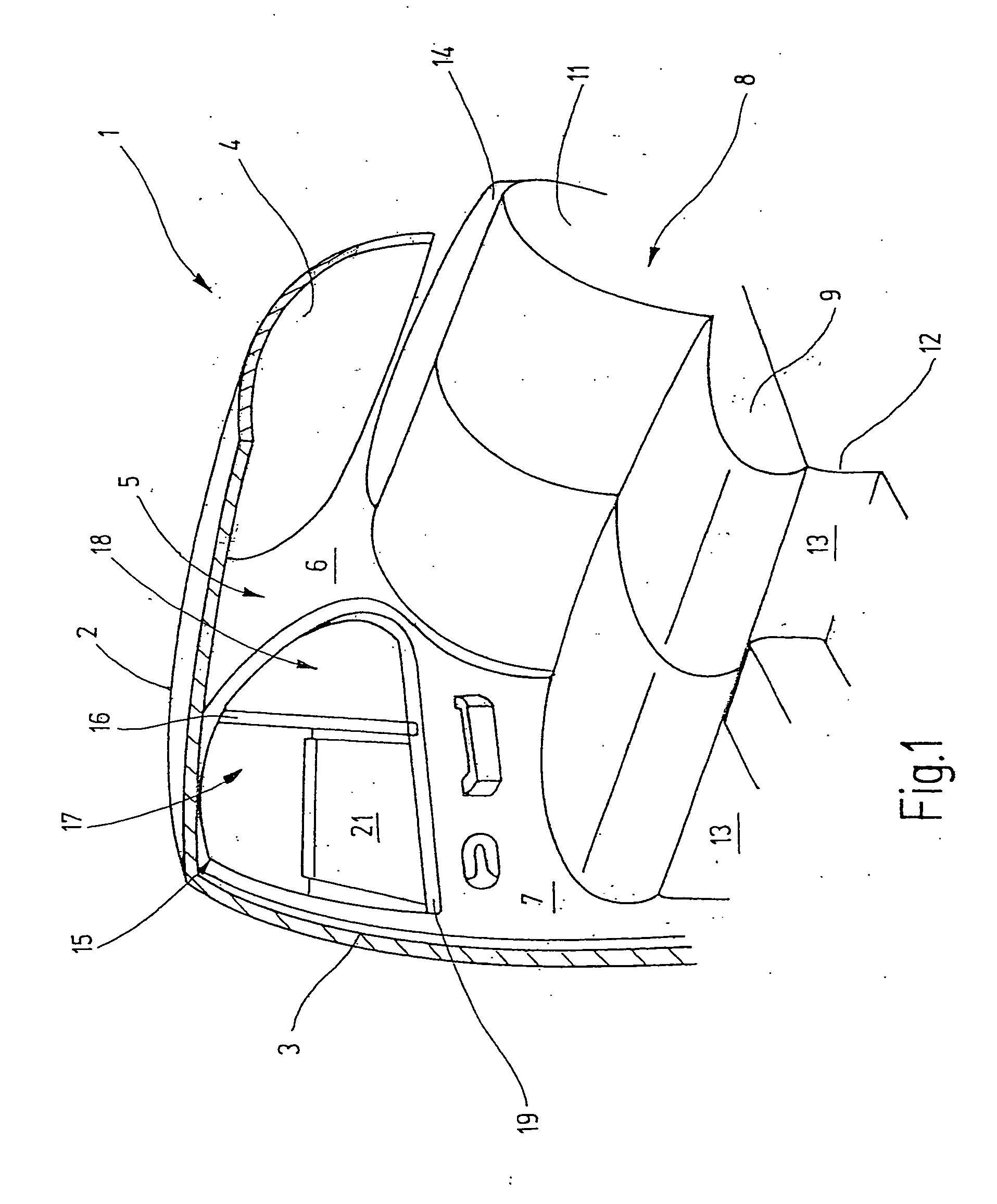
[0018] Referring now more particularly to FIG. 1 of the drawings, there is shown an illustrative motor vehicle having a side window roller blind assembly in accordance with the invention. FIG. 1 represents a cut-away rear area of a passenger car. The figure illustrates a view towards the right-side interior, which is the mirror image of the not-shown left-side interior. The view is simplified; for example, car body interior structures such as braces and attachment means are not shown because their illustration is not necessary for understanding the invention.

[0019] The illustrated car body section 1 has a roof 2 from which a B-column 3 extends downwardly at the side to a an underbody. A corresponding B-column is provided on the opposite side of the vehicle. The roof 2 transitions at its rear edge into a rear window 4. At the side, the rear window 4 ends at a C-column 5 located at a distance from the B-column 3. The C-column 5 carries an interior lining 6.

[0020] Between the B-colum...


PUM


Abstract

A window roller blind assembly for motor vehicles which includes a roller blind that can be drawn from a wind-up shaft by a motor driven driving element engageable with a pull rod of the roller blind. To prevent pinching as a result of the pull rod engaging an obstacle during operation of the roller blind assembly, an electrical system is provided for monitoring operation of the roller blind motor. The system is operable for switching off current to the motor when a preset value is exceed, which is interpreted as a signal that pinching or squeezing of an obstacle is occurring.

Description

FIELD OF THE INVENTION [0001] This present invention relates generally to window shades, and more particularly, to power operated window shades for motor vehicles. BACKGROUND OF THE INVENTION [0002] Electronically operated roller sunshades are increasingly being used in motor vehicles. These roller sunshades are used on the side windows of rear doors, the rear window, or the glass sunroof. A roller blind for rear windows, for example, is known from DE 103 51 040 A1. The rear window roller blind described therein comprises a winding shaft that is rotatably supported underneath the rear window shelf, with one edge of the roller blind shade fixed on the winding shaft. The free end of the roller blind material is connected to a pull or tension rod. The pull rod is tubular and accommodates the neck of two guide pieces, which are provided on each end of the rod. The guide pieces run in guide rails which are arranged in the interior panel beside the rear window. The pull rod is driven via ...

Claims


Application Information

Patent Timeline
Patent Type & Authority Applications(United States)
IPC IPC(8): B60J1/20
CPCB60J1/2016B60J1/2019B60J1/2027B60J1/2055E05F15/41E05Y2400/554E06B9/88E05Y2900/55B60J1/2086E05Y2900/106E05Y2900/00B60J1/20B60J3/02B60J3/00
Inventor HANSEN, MELFSCHLECHT, WERNER P.
Owner BOS
Why Eureka
Try Eureka