
Metering and dispensing device

a technology of metering and dispensing device, which is applied in the direction of measurement device, liquid/fluent solid measurement, instruments, etc., can solve the problems of unsanitary, burdensome user, and inefficient above-the-line method of using measuring spoon or cup, so as to minimize the possibility of spillage, contamination, and dispensing unwanted effects

Inactive Publication Date: 2007-01-04
RANNEY FREDRIK J
View PDF28 Cites 33 Cited by
  • Summary
  • Abstract
  • Description
  • Claims
  • Application Information

AI Technical Summary

Benefits of technology

[0007] The device minimizes the user's contact with the product during the metering and dispensing operation. The device and the container can subsequently be stored away as a single unit.
[0008] The device of the present invention enables precise metering of the free flowing product or material in a simple and prompt manner, while substantially minimizing the possibility of spillage, contamination, and unwanted dispensing. The device of the present invention is especially suitable for use by those with limited dexterity or “unsteady” hands such as children, elderly people and the infirm. The device of the present invention is further compact, simple to operate, and has a pleasing appearance.

Problems solved by technology

The above method of using the measuring spoon or cup is often inefficient, unsanitary and burdensome to the user.

Method used


Image

  • Metering and dispensing device
  • Metering and dispensing device
  • Metering and dispensing device

Examples


second embodiment

[0063] Referring to FIG. 8, a coupling adapter 72 is shown for the present invention. The coupling adapter 72 is designed to enable the device 10 to be coupled to externally threaded containers with larger diameter openings. The coupling adapter 72 includes an externally threaded portion 74 extending along an upper opening 78, and an internally threaded portion 76 extending along a lower opening 80 for attachment to a larger diameter opening of the container. The device 10 is attached to opening 78 of the adapter 72 through threaded engagement with the externally threaded portion 74. Correspondingly, the container is attached to the opening 80 of the adapter 72 through the threaded engagement with the internally threaded portion 76.

third embodiment

[0064] Referring to FIG. 9, a coupling adapter 82 is shown for the present invention. The coupling adapter 82 is designed to enable the device 10 to be coupled to a container 84 having a snap-on type of opening 86. The container 84 includes a flange portion 96 extending along the opening 86 that is capable of accommodating snap-on lids (not shown). The coupling adapter 82 includes an externally threaded portion 88 extending along an upper opening 90, and a ledge portion 92 extending along a lower opening 96 for attachment to a snap-on opening 86 of the container 84. The ledge portion 92 of the coupling adapter 82 engages with the flange portion 96 of the container 84 for secure coupling therebetween. The device 10 via its threaded portion 22 screws onto threads 88 of coupling adapter 82.

[0065] Referring to FIG. 10, a flowchart 100 is shown to depict the operation steps of the metering and dispensing device 10. With reference to FIGS. 1 through 6E, the overall operation of the device...


PUM


Abstract

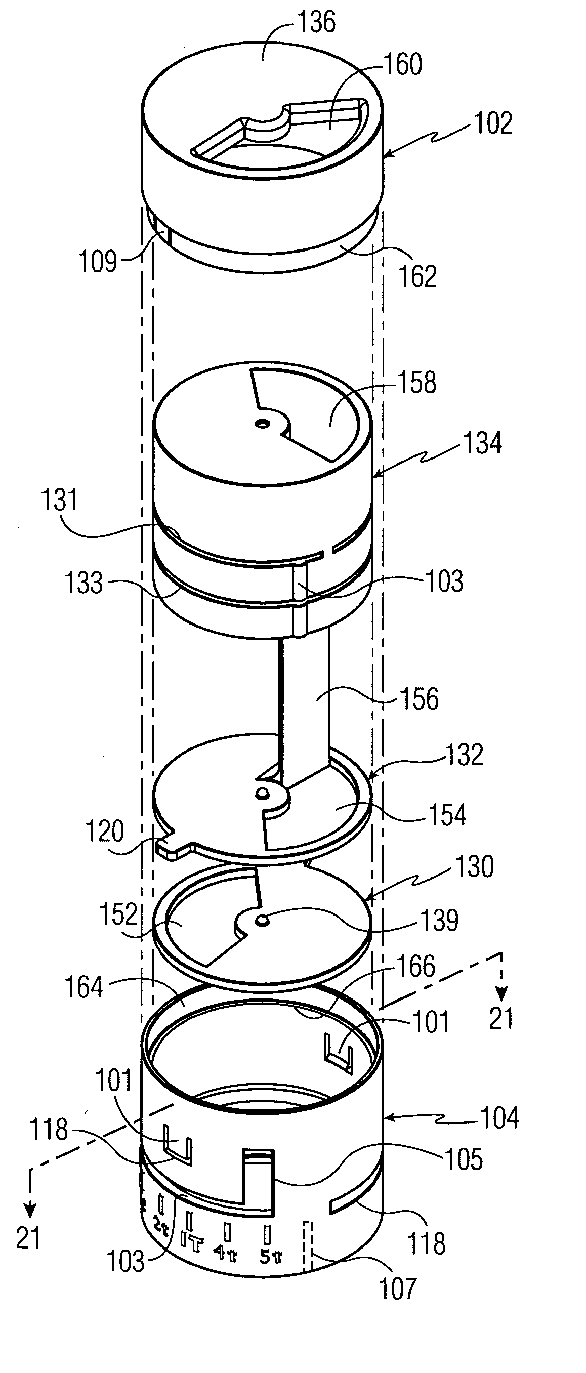
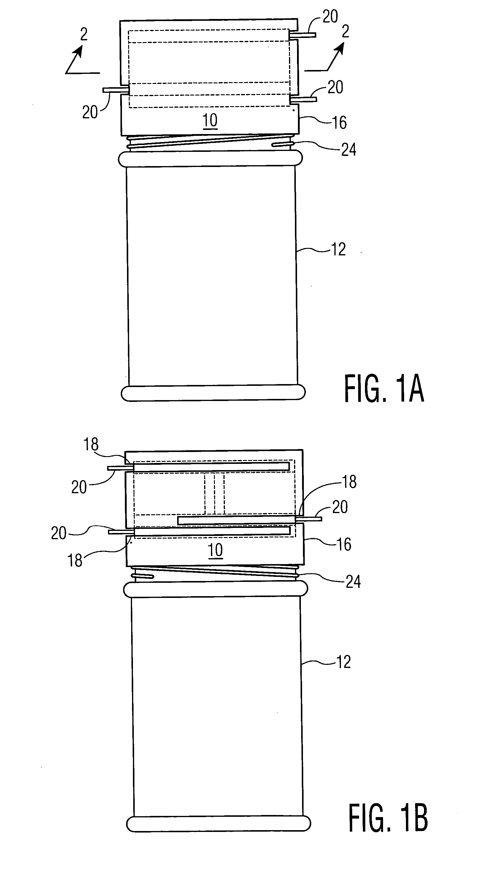
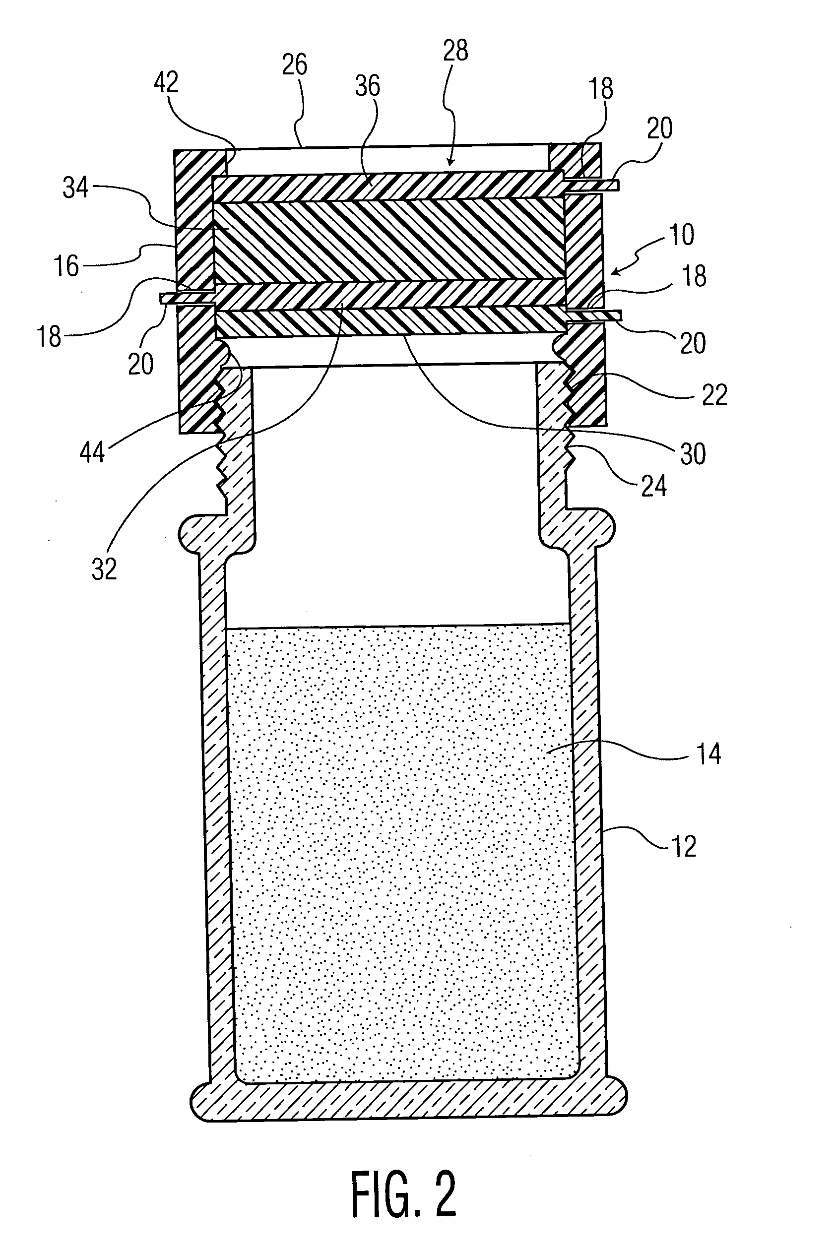
A metering and dispensing device for free flowing materials includes a volume body having first and second ends, and a volumetric channel extending therethrough. The second end of the volume body is adapted for attachment to the opening of a container holding the free flowing material. The device further includes a measuring partition operatively associated with the second end of the volume body. The measuring partition includes a barrier lip portion extending therefrom into the volumetric channel, and a measuring opening selectively movable from a closed position to an open position relative to the volumetric channel, wherein the selective movement of the measuring opening simultaneously causes the barrier lip portion to vary the volume of the volumetric channel relative to the measuring opening. The device further includes a feed partition proximate the second end of the volume body, operatively associated with the measuring partition, the feed partition including a feed opening selectively movable from a closed position to an open position relative to the measuring opening. The device also includes a discharge partition operatively associated with the first end of the volume body, which includes a discharge opening selectively movable from a closed position to an open position relative to the volumetric channel.

Description

FIELD OF THE INVENTION [0001] The present invention relates generally to particulate measuring devices, and more particularly to an improved metering and dispensing device for free flowing materials including particulates, granulates and powders. BACKGROUND OF THE INVENTION [0002] People working in the culinary arts, and homemakers have used measuring spoons over the years to measure free flowing materials of various kinds including a flake or particulate material, such as for example, granular or powder materials, including spices, flour, sugar, salt, pepper, artificial sweeteners, and so forth, for example. Typically, a person measures a quantity of a powder or granular material by selecting a measuring spoon or cup having a desired capacity. The material to be measured is poured into the selected measuring spoon or cup to full volume. The user thereafter dispenses the material from the spoon or cup in the measured amount as desired. [0003] The above method of using the measuring ...

Claims


Application Information

Patent Timeline
Patent Type & Authority Applications(United States)
IPC IPC(8): G01F11/28
CPCG01F11/261G01F11/46G01F11/268
Inventor RANNEY, FREDRIK J.
Owner RANNEY FREDRIK J
Learn More