Electromagnetic valve, particularly for a braking system of a motor vehicle

a technology of electromagnetic valves and braking systems, which is applied in the direction of valve operating means/release devices, magnetic bodies, braking systems, etc., can solve the problems of affecting the replicability of the position of the tappet, and achieve the advantages of the replicability of the valve, saving material, weight and expenses, and being produced and assembled inexpensively.

Active Publication Date: 2007-01-04
ROBERT BOSCH GMBH
View PDF11 Cites 11 Cited by
  • Summary
  • Abstract
  • Description
  • Claims
  • Application Information

AI Technical Summary

Benefits of technology

[0002] In known brake systems, electromagnetic valves are used particularly as inlet or switchover valves, in order to furnish anti-lock, traction control or electronic stability program functions for brakes of an associated motor vehicle. Known electromagnetic valves have an elongated tappet, which is guided axially displaceably in a substantially hollow-cylindrical tappet guide. A likewise hollow-cylindrical sealing seat is press-fitted into the hollow-cylindrical tappet guide, and a sealing body located on one end of the tappet can then strike this sealing seat and hence provide sealing. The press-fitting of the sealing seat into the tappet guide can change the geometry of the entire arrangement for adapting and adjusting the desired valve function. In particular, when the sealing seat is open, an existing air gap in the axial direction between the tappet and the tappet guide can be adjusted.
[0017] A sealing seat is not press-fitted into the tappet guide of the invention, and thus the tappet guide need not absorb corresponding pressure forces and can optionally be embodied as comparatively thin in the region of the sealing seat. This saves material, weight and expenses. Moreover, at least one radial bore can advantageously be embodied on the tappet guide of the invention, in the region of the sealing seat, by which bore a fluid flowing through the sealing seat can be carried away to the outside of the tappet guide. In this outflow of the fluid, its flow is deflected only once, by an angle of 90°. The flow resistance is correspondingly reduced. Furthermore, the tappet guide then also takes on the function of “conducting the outflow”, so that other components of the electromagnetic valve of the invention, which have previously taken on this function, can be embodied correspondingly more simply. For instance, a plastic insert, provided in known valves, on the side of the sealing seat facing away from the tappet can be designed correspondingly simply.

Problems solved by technology

Each of these interfaces involves dimensional, shape and positional tolerances, which impairs the replicability of the position of the tappet that is important for regulating pressure.

Method used


Image

  • Electromagnetic valve, particularly for a braking system of a motor vehicle
  • Electromagnetic valve, particularly for a braking system of a motor vehicle
  • Electromagnetic valve, particularly for a braking system of a motor vehicle

Examples


Embodiment Construction

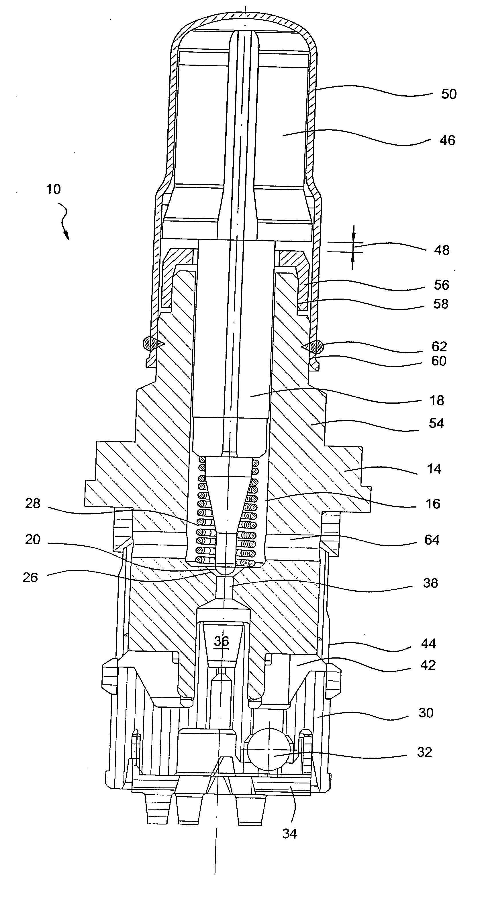
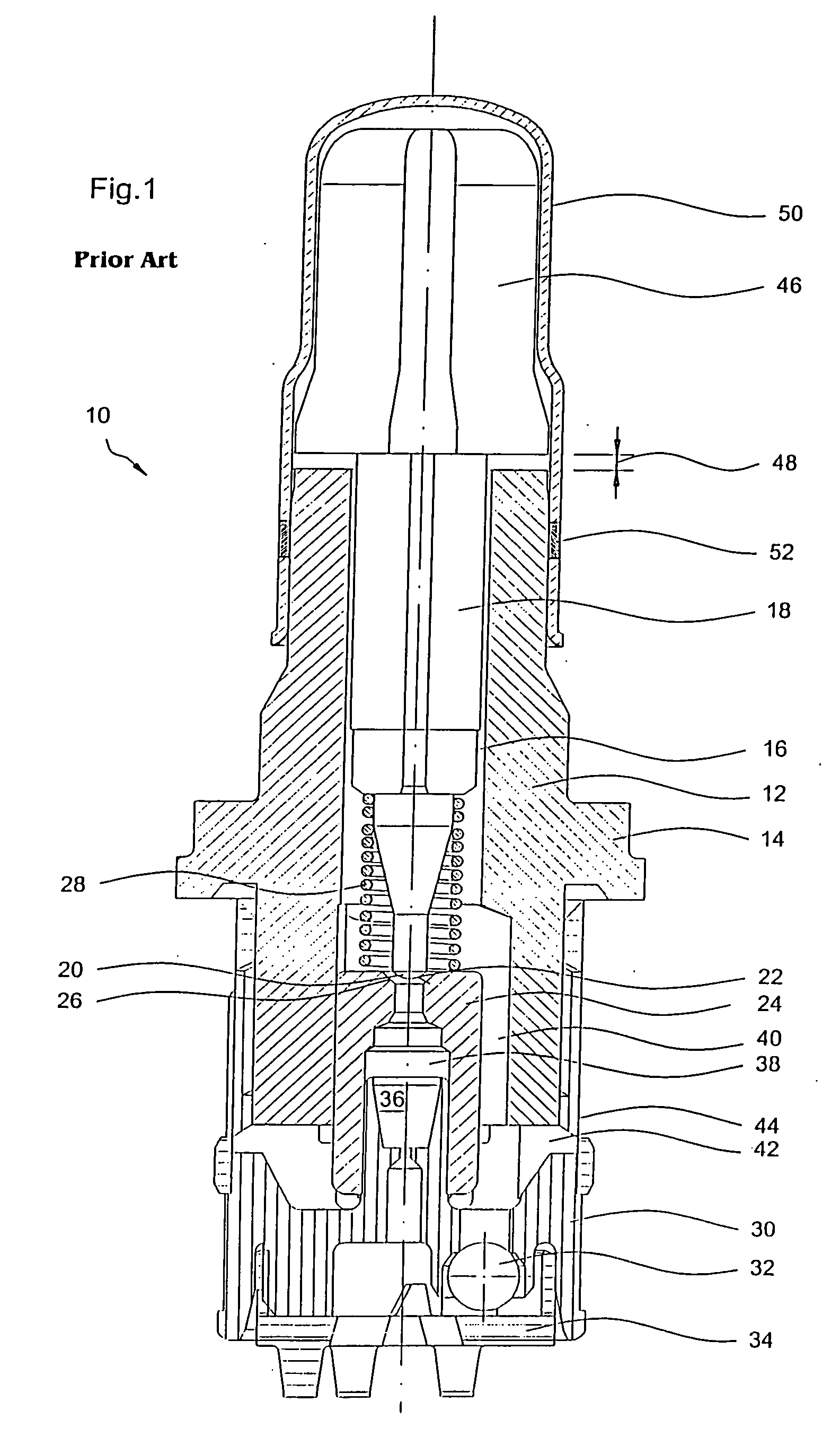
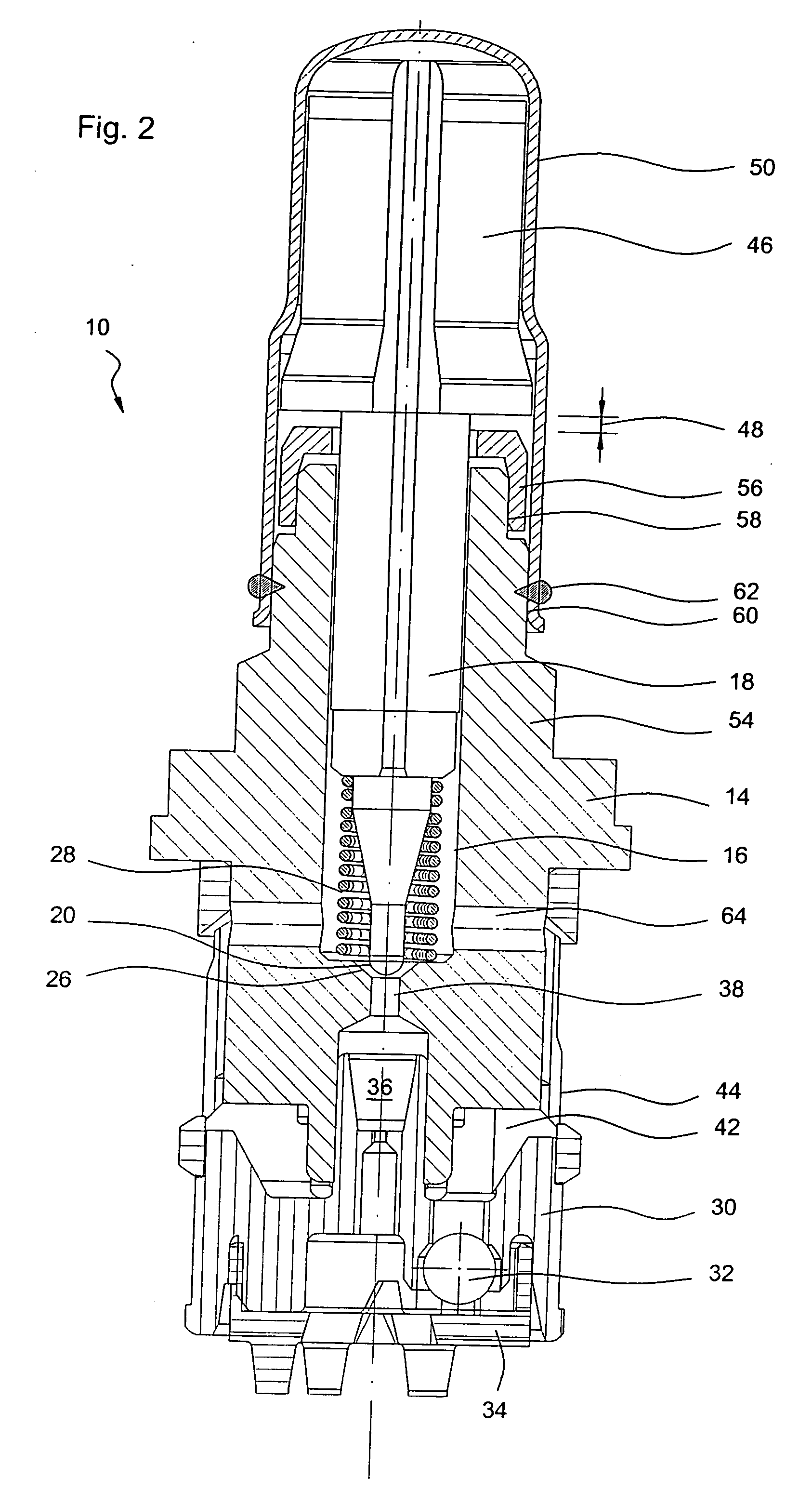
[0023] In FIG. 1, an electromagnetic valve 10 of the prior art is shown. As its central component, the valve 10 has a substantially hollow-cylindrical tappet guide 12, or valve insert, on the outside of which a collar 14 is embodied approximately in the middle of its length and a through opening 16 is embodied in the longitudinal direction in the interior. In the through opening 16, a substantially circular-cylindrical tappet 18 is supported displaceably in the longitudinal direction of the tappet guide 12. On the lower end of the tappet 18, in terms of FIG. 1, a sealing body 20 is provided, which has a spherical-segment-shaped surface 22 that bulges downward.

[0024] Diametrically opposite the sealing body 20, there is a sealing seat 24 or sealing body which is designed essentially hollow-cylindrically and which has a frustoconical surface 26 opposite the spherical-segment-shaped surface 22. A spiral spring 28, which acts as a compression spring and is braced on the sealing seat 24,...


PUM


Abstract

An electromagnetic valve is provided with an elongated tappet guided axially displaceably in a tappet guide, and with a sealing body, embodied on the tappet, that can seal against a sealing seat. So that the valve can be produced more economically yet can be regulated more precisely, the sealing seat and the tappet guide are embodied in one piece. The adjustability of the valve is assured in particular by an adjusting ring.

Description

[0001] The invention relates to an electromagnetic valve, in particular for a brake system of a motor vehicle, having an elongated tappet, which is guided axially displaceably in a tappet guide, and having a sealing body, embodied on the tappet, that can seal against a sealing seat. [0002] In known brake systems, electromagnetic valves are used particularly as inlet or switchover valves, in order to furnish anti-lock, traction control or electronic stability program functions for brakes of an associated motor vehicle. Known electromagnetic valves have an elongated tappet, which is guided axially displaceably in a substantially hollow-cylindrical tappet guide. A likewise hollow-cylindrical sealing seat is press-fitted into the hollow-cylindrical tappet guide, and a sealing body located on one end of the tappet can then strike this sealing seat and hence provide sealing. The press-fitting of the sealing seat into the tappet guide can change the geometry of the entire arrangement for a...

Claims


Application Information

Patent Timeline
Patent Type & Authority Applications(United States)
IPC IPC(8): F16K31/02B60T8/36B60T15/02F16K31/06
CPCB60T8/363F16K31/0655B60T15/028
Inventor KRATZER, DIETMAR
Owner ROBERT BOSCH GMBH
Why Eureka
Try Eureka