Spring-loaded stay-tight retaining nut assembly for a tubing fitting

Inactive Publication Date: 2007-01-04
IMTEC ACCULINE
View PDF16 Cites 16 Cited by
  • Summary
  • Abstract
  • Description
  • Claims
  • Application Information

AI Technical Summary

Benefits of technology

[0011] The present invention generally comprises a tubing connection that overcomes the drawbacks of the prior art as described above. In particular, the inv

Problems solved by technology

The Teflon tube cannot change shape and extrude backwards through t

Method used


Image

  • Spring-loaded stay-tight retaining nut assembly for a tubing fitting
  • Spring-loaded stay-tight retaining nut assembly for a tubing fitting
  • Spring-loaded stay-tight retaining nut assembly for a tubing fitting

Examples


Embodiment Construction

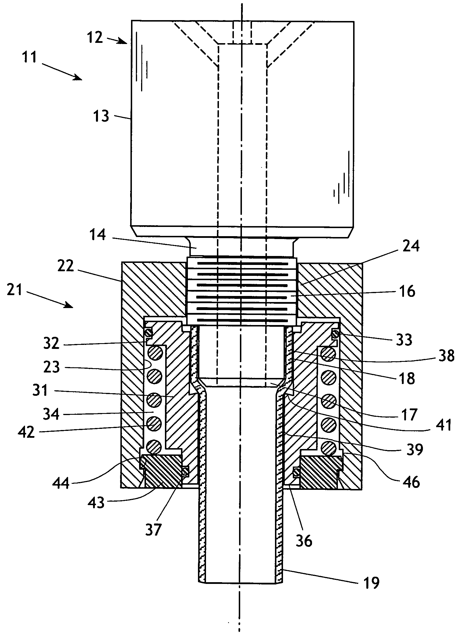
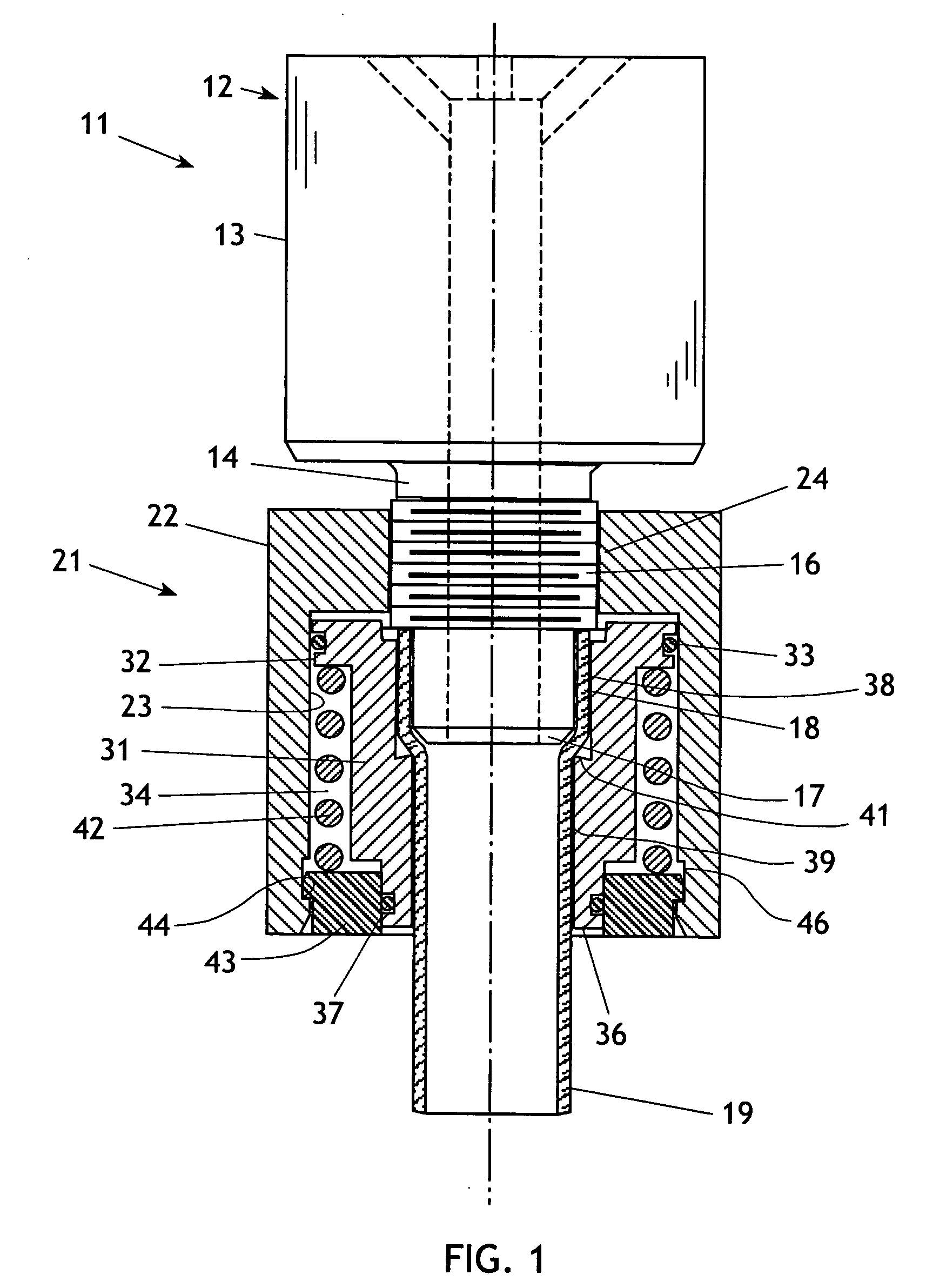
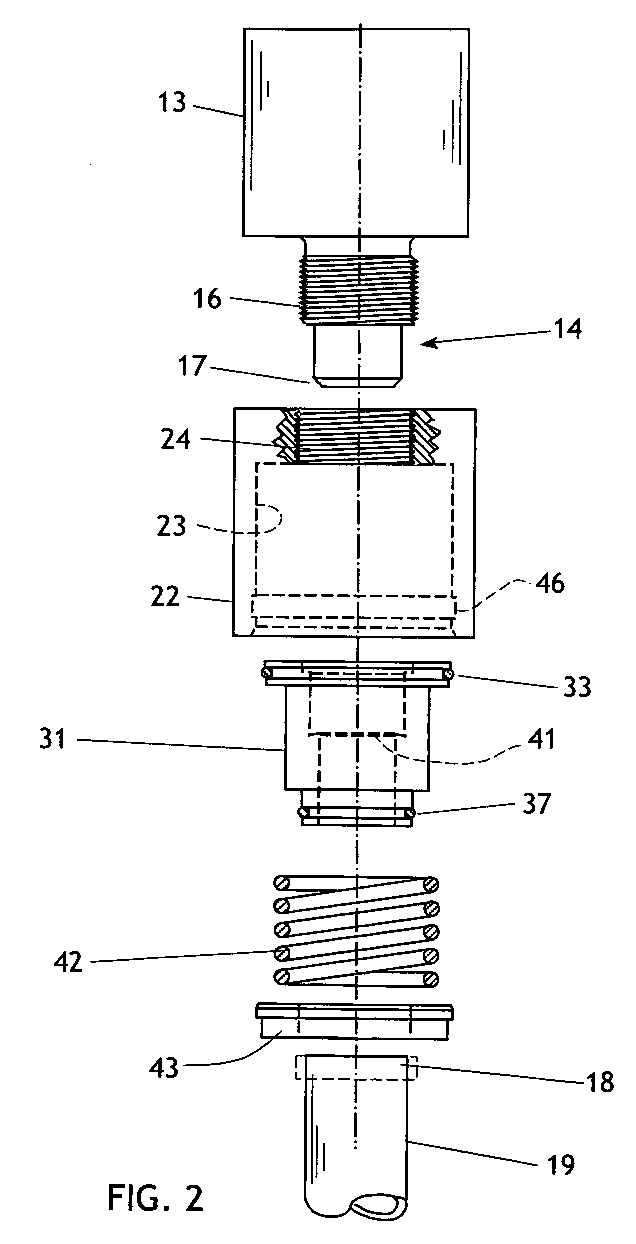
[0019] The present invention generally comprises a unique connector assembly having a fitting that receives a flared tubing end and secures it with a compression nut. It is intended for use in harsh chemical environments, where the presence of corrosive liquids and the potential for contamination of process chemistry necessitates the use of Teflon components. In the following description it is presumed that components are made of Teflon or an equivalent polymer material that is inert with respect to a wide range of harsh chemicals and solvents.

[0020] More particularly, as shown in FIGS. 1 and 2, one embodiment of the invention is designed to operate with a typical pressurized fluid (liquid or gas) connector assembly 11 having a male connector fitting 12. The fitting 12 includes a body 13, and nipple 14 extending therefrom, with external threads 16 and a tapered end 17. The end 18 of resilient tubing 19 is dimensioned to expand and slidably engage the nipple 14; this arrangement bei...


PUM


Abstract

A tubing connection provides a unique nut assembly that does not loosen or leak when exposed to the initial heat/cool cycles of a chemistry setup. The nut assembly includes a outer housing portion, and a concentric inner locking ferrule. A cavity defined between the inner and outer portion houses a stainless steel spring secured therein by a snap-engaged spring retainer. As the outer nut is rotated on the threads of the fitting, it drives the spring retainer toward the ferrule, thereby compressing the spring and causing it to maintain the engagement of the tubing end on the connector fitting.

Description

CROSS-REFERENCE TO RELATED APPLICATIONS [0001] This application claims the benefit of the priority date of Provisional Application Ser. No. 60 / 695,560, filed Jun. 29, 2005.FEDERALLY SPONSORED RESEARCH [0002] Not applicable. SEQUENCE LISTING, ETC ON CD [0003] Not applicable. BACKGROUND OF THE INVENTION [0004] 1. Field of the Invention [0005] This invention relates to tubing connectors for chemical use and, more particularly, to tubing connectors fabricated of relatively soft polymer materials such as Teflon. [0006] 2. Description of Related Art [0007] In chemistry laboratories, chemical processing installations, and other users of chemistry equipment, a ubiquitous component in chemical processing layouts is the common tubing connector. Most processing is conducted in a liquid-based processing scheme and whether for solvents and solutions, feedstock or waste flow, washes or etches, the instruments, pumps, reaction vessels, tanks, and valves are interconnected using inert tubing and tu...

Claims


Application Information

Patent Timeline
IPC IPC(8): F16L39/00
CPCF16B7/182F16L19/005F16B37/00
Inventor STRUVEN, KENNETH C.
Owner IMTEC ACCULINE
Why Eureka
Try Eureka