Boundary acoustic wave device

Active Publication Date: 2007-01-04
MURATA MFG CO LTD
View PDF4 Cites 13 Cited by
  • Summary
  • Abstract
  • Description
  • Claims
  • Application Information

AI Technical Summary

Benefits of technology

[0017] To overcome the problems described above, preferred embodiments of the present invention provide a boundary acoustic wave device using SH boundary waves, which provides sufficiently large electromechanical coupling c

Problems solved by technology

The package having such a hollow portion inevitably increases the cost of the surface acoustic wave device.
Specifically, the loss of boundary acoustic waves accompanied with their propagation, that is, propagation loss adversely affects the insertion loss of the boundary acoustic wave filter, the resonant resistance, and the imp

Method used


Image

  • Boundary acoustic wave device
  • Boundary acoustic wave device
  • Boundary acoustic wave device

Examples


example 1

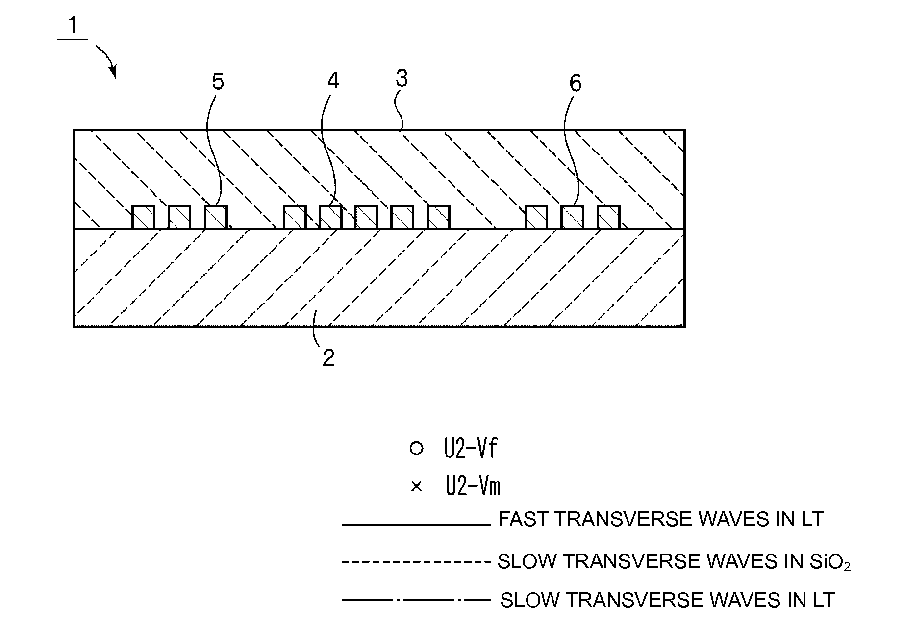
[0102] An LiTaO3 substrate with Euler angles of (0°, 90°, 0°), that is a Y-plate X-propagating LiTaO3 substrate, was prepared as the piezoelectric body 2. This LiTaO3 substrate is highly piezoelectric. The dielectric body 3 was formed of SiO2. SiO2 is easy to form into a thin layer. The boundary wave device structured according to preferred embodiments of the present invention propagates boundary waves while distributing a portion of the vibrational energy in the LiTaO3 substrate and the SiO2 body. Since the SiO2 body has a positive frequency temperature coefficient TCF that cancels the negative TCF of the LiTaO3 substrate, the temperature dependence is improved.

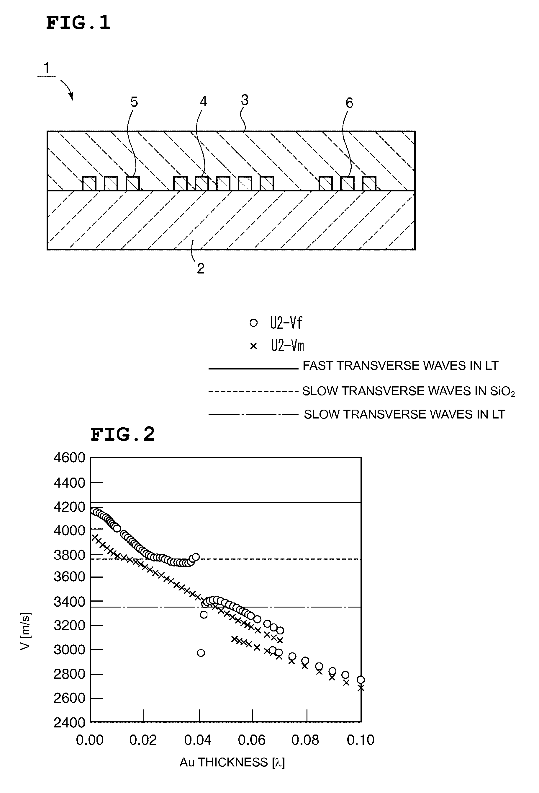
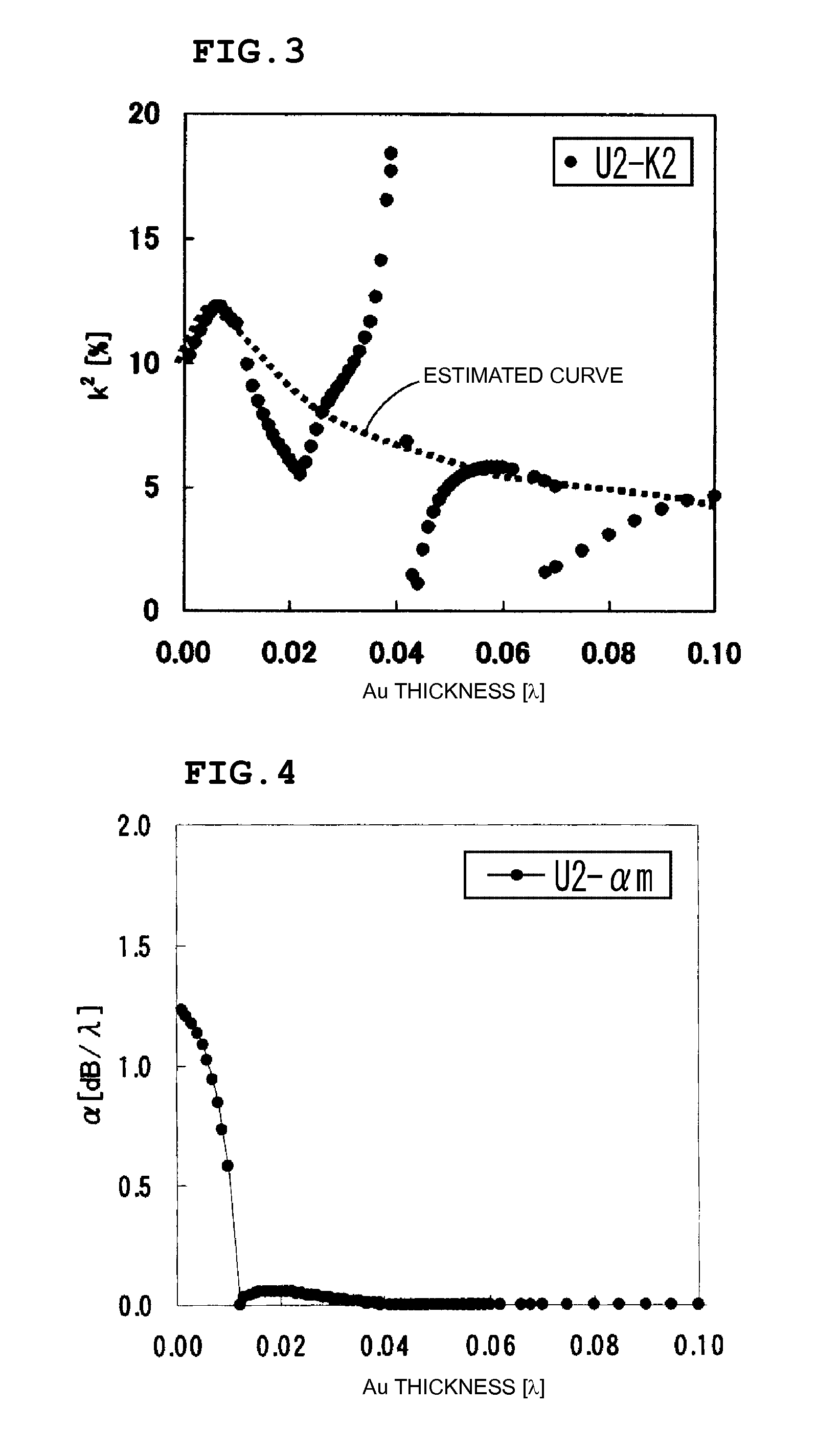
[0103] The relationships were examined between the thickness of the electrodes and the acoustic velocity V, electromechanical coupling coefficient k2, propagation loss α, frequency temperature coefficient TCF, and power flow angle PFA, using electrodes made of various materials having different densities between the piezoel...


PUM


Abstract

A boundary acoustic wave device includes a dielectric body disposed over one surface of a LiTaO3 piezoelectric body, and an electrode including an IDT and reflectors at the boundary between the piezoelectric body and the dielectric body. The thickness of the electrode is set so that the acoustic velocity of the SH boundary acoustic waves is less than the acoustic velocities of slow transverse waves propagating in the dielectric body and slow transverse waves propagating in the piezoelectric body.

Description

BACKGROUND OF THE INVENTION [0001] 1. Field of the Invention [0002] The present invention relates to boundary acoustic wave devices using SH boundary acoustic waves, and particularly to a boundary acoustic wave device including an electrode disposed at the boundary between a LiTaO3 piezoelectric body and a dielectric body. [0003] 2. Description of the Related Art [0004] A variety of surface acoustic wave devices have been used for cellular phone RF or IF filters, VCO resonators, television VIF filters, and other devices. Surface acoustic wave devices use surface acoustic waves propagating along a surface of a medium, such as Rayleigh waves or first leaky waves. [0005] Since the surface acoustic waves propagate along a surface of a medium, they are sensitive to changes in the surface conditions. In order to protect the surface of the medium along which surface acoustic waves propagate, the surface acoustic wave element is hermetically enclosed in a package having a hollow portion in ...

Claims


Application Information

Patent Timeline
IPC IPC(8): H03H9/15H01L41/09H01L41/18H03H9/02H03H9/145H03H9/25
CPCH03H9/0222
Inventor KANDO, HAJIME
Owner MURATA MFG CO LTD
Why Eureka
Try Eureka