Surface acoustic wave device including electrode fingers partially disposed in grooves in a piezoelectric substrate

a surface acoustic wave and electrode finger technology, which is applied in piezoelectric/electrostrictive device details, piezoelectric/electrostrictive/magnetostrictive devices, piezoelectric/electrostriction/magnetostriction machines, etc., can solve the problem of acoustic velocity of surface acoustic wave tending to decrease, and achieves increased thickness, decreased reflection coefficient, and increased electrical coupling coefficient.

Active Publication Date: 2012-05-01
MURATA MFG CO LTD
View PDF15 Cites 1 Cited by
  • Summary
  • Abstract
  • Description
  • Claims
  • Application Information

AI Technical Summary

Benefits of technology

[0048]That is, according to this preferred embodiment, it is possible to provide a surface acoustic wave device which has a large electromechanical coupling coefficient (k2), a low insertion loss, and high resistance to static electricity. Note that the advantageous effects described above can be obtained regardless of the Euler angles of the piezoelectric substance 10.
[0049]In contrast, when at least a portion of the first electrode layer 21 having a large (ρ3×C44)1 / 2 value is disposed at a position higher than the upper opening of the groove 10a, the electromechanical coupling coefficient (k2) tends to be decreased.
[0050]Furthermore, when the second electrode layer 22 having a small (ρ3×C44)1 / 2 value is disposed inside the groove 10a, the reflection coefficient tends to be decreased.
[0051]Furthermore, when, without providing the second electrode layer 22 having a small (ρ3×C44)1 / 2 value, only the first electrode layer 21 having a large (ρ3×C44)1 / 2 value is provided with an increased thickness so as to decrease the resistance of the first electrode fingers 31b and the second electrode fingers 32b, the acoustic velocity of the surface acoustic wave is decreased. Therefore, the pitch of the electrode fingers 31b and 32b must be decreased. Consequently, the resistance to static electricity is decreased and the manufacturability of the surface acoustic wave device is decreased.
[0052]From the standpoint of further increasing the electromechanical coupling coefficient (k2), further decreasing the insertion loss, and further increasing the resistance to static electricity, preferably, the first electrode layer 21 and the second electrode layer 22 are preferably configured so as to satisfy the relationship (ρb3×C44b)1 / 2<6.54×10¹⁰≦(ρa3×C44a)1 / 2, and more preferably, so as to satisfy the relationship (ρb3×C44b)1 / 2<6.54×10¹⁰≦(ρa3×C44a)1 / 2<5.0×10¹¹.
[0053]The structure of each of the first electrode layer 21 and the second electrode layer 22 is not particularly limited as long as the relationship (ρa3×C44a)1 / 2>(ρb3×C44b)1 / 2 is satisfied. Each of the first electrode layer 21 and the second electrode layer 22 may be made of a metal film or a laminated body including a plurality of metal films.

Problems solved by technology

However, when the density of the IDT electrode is increased or the thickness of the IDT electrode is increased, the acoustic velocity of the surface acoustic wave tends to decrease.

Method used


Image

  • Surface acoustic wave device including electrode fingers partially disposed in grooves in a piezoelectric substrate
  • Surface acoustic wave device including electrode fingers partially disposed in grooves in a piezoelectric substrate
  • Surface acoustic wave device including electrode fingers partially disposed in grooves in a piezoelectric substrate

Examples


example 1

Conditions in Example 1

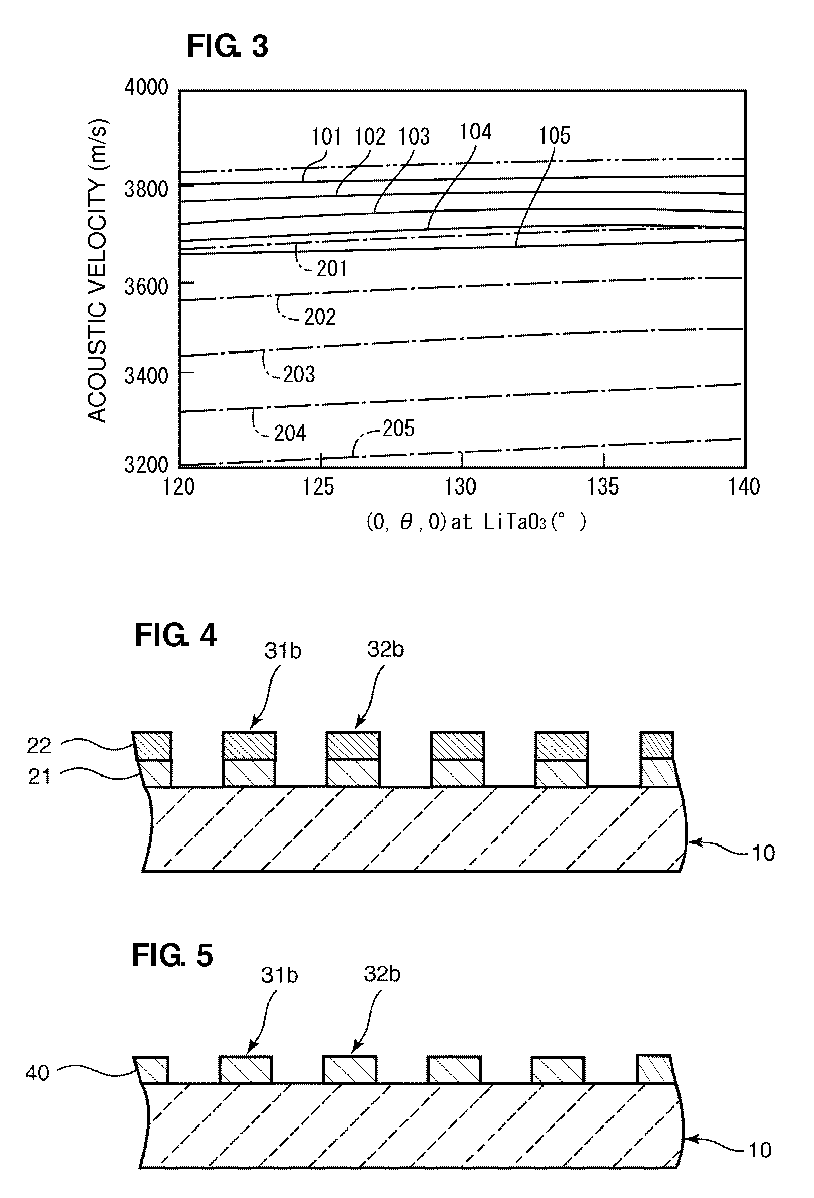
Piezoelectric substance 10: LiTaO3 substrate having Euler angles (0°, θ, 0°)

First electrode layer 21: Cu film ((ρ3×C44)1 / 2=about 1.91×10¹¹)

First electrode layer 21 thickness normalized to wavelength (h / λ): about 0.1

Second electrode layer 22: Al film ((ρ3×C44)1 / 2=about 2.27×10¹⁰)

Second electrode layer 22 thickness normalized to wavelength (h / λ): about 0.01 to about 0.05

[0066]In Comparative Example 1, as shown in FIG. 4, surface acoustic wave devices were fabricated under the same conditions as those in Example 1, except that grooves were not provided in the piezoelectric substance 10 and the first electrode layer 21 and the second electrode layer 22 were formed on the piezoelectric substance 10. The acoustic velocity, the stop band, and the fractional bandwidth at θ of the Euler angles of the piezoelectric substances 10 in the surface acoustic wave devices 1 were measured. The measurement results of the acoustic velocity are shown by dashed-dotted lines in the ...

modified example

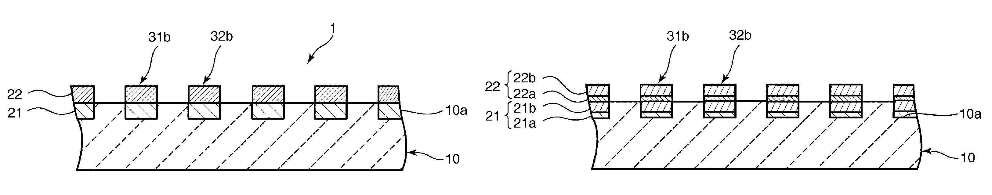
[0086]FIG. 17 is a schematic cross-sectional view of a surface acoustic wave device according to a modified example of a preferred embodiment of the present invention. As shown in FIG. 17, a first electrode layer 21 may preferably include a first metal film 21a and a second metal film 21b, and a second electrode layer 22 may preferably include a first metal film 22a and a second metal film 22b. Even in this case, when the (ρa3×C44a)1 / 2 value of the first electrode layer 21 is greater than the (ρb3×C44b)1 / 2 value of the second electrode layer 22, substantially the same advantageous effects as those in the preferred embodiments described above are obtained.

[0087]In addition, in the modified example, ρa is obtained by dividing the sum of the product of the density and the thickness of the first metal film 21a and the product of the density and the thickness of the second metal film 21b by the thickness of the first electrode layer 21. C44a is obtained by dividing the sum of the product...


PUM


Abstract

A surface acoustic wave device has a large electromechanical coupling coefficient, a low insertion loss, and high resistance to static electricity. In the surface acoustic wave device, a piezoelectric substance includes a plurality of grooves. Each electrode finger of an IDT electrode includes a first electrode layer disposed in the grooves and a second electrode layer disposed on the first electrode layer and located at a position higher than the upper opening of the grooves. In a surface acoustic wave device, the one-half power of the product of the cube of the average density (ρa) of the first electrode layer and the average stiffness (C44a) of the first electrode layer [(ρa3×C44a)1 / 2] is larger than the one-half power of the product of the cube of the average density (ρb) of the second electrode layer and the average stiffness (C44b) of the second electrode layer [(ρb3×C44b)1 / 2].

Description

BACKGROUND OF THE INVENTION[0001]1. Field of the Invention[0002]The present invention relates to a surface acoustic wave device, for example, used for a resonator or a band-pass filter.[0003]2. Description of the Related Art[0004]In duplexers (DPXs) and RF filters used for mobile communication systems and other suitable systems, both a broad bandwidth and good temperature characteristics are required. As a surface acoustic wave device that has both a broad bandwidth and good temperature characteristics, for example, International Publication No. WO2006 / 011417 discloses a surface acoustic wave device including an IDT electrode made of Al embedded in a LiTaO3 substrate. By embedding an IDT electrode in a piezoelectric substance as in the surface acoustic wave device disclosed in International Publication No. WO2006 / 011417, a large electromechanical coupling coefficient (k2) is obtained. As a result, a broad bandwidth is achieved.[0005]In a surface acoustic wave device in which an IDT ...

Claims


Application Information

Patent Timeline
Patent Type & Authority Patents(United States)
IPC IPC(8): H03H9/25H01L41/04
CPCH03H9/02559H03H9/14541
Inventor KIMURA, TETSUYAKADOTA, MICHIO
Owner MURATA MFG CO LTD
Why Eureka
Try Eureka