Liquid crystal display device

a liquid crystal display and display device technology, applied in the direction of static storage, digital storage, instruments, etc., can solve the problems of difficult transistor discharge of n-th stage, easy deterioration of the transistor, and difficult discharge of the transistor, so as to improve the lifetime of the component in the lcd device

Active Publication Date: 2007-01-04
LG DISPLAY CO LTD
View PDF6 Cites 14 Cited by
  • Summary
  • Abstract
  • Description
  • Claims
  • Application Information

AI Technical Summary

Benefits of technology

[0026] An object of the present invention is to improve a lifetime of a component in an LCD device.

Problems solved by technology

However, as the transistor for discharge is deteriorated, the pull-up transistor generates the multi-output due to the coupling effect.
However, the dummy stage doesn't supply the scan pulse to the gate line.
Accordingly, the transistor for discharge of the n-th stage, to which the scan pulse is applied, can be easily deteriorated.
In this case, it is difficult for the transistor to perform the discharge of the first node of the n-th stage.
The multi-output is abnormal, whereby the transistor for discharge provided in the (n−1)-th stage is easily deteriorated.
As a result, the discharge transistors, provided in the stages, deteriorate, thereby generating the multi-output.
That is, the picture quality of the LCD panel deteriorates due to one stage outputting scan pulses several times during one frame period.

Method used


Image

  • Liquid crystal display device
  • Liquid crystal display device
  • Liquid crystal display device

Examples


Embodiment Construction

[0041] Reference will now be made in detail to the preferred embodiments of the present invention, examples of which are illustrated in the accompanying drawings. Wherever possible, the same reference numbers will be used throughout the drawings to refer to the same or like parts.

[0042] Hereinafter, a liquid crystal display (LCD) device according to the preferred embodiment of the present invention will be described with reference to the accompanying drawings.

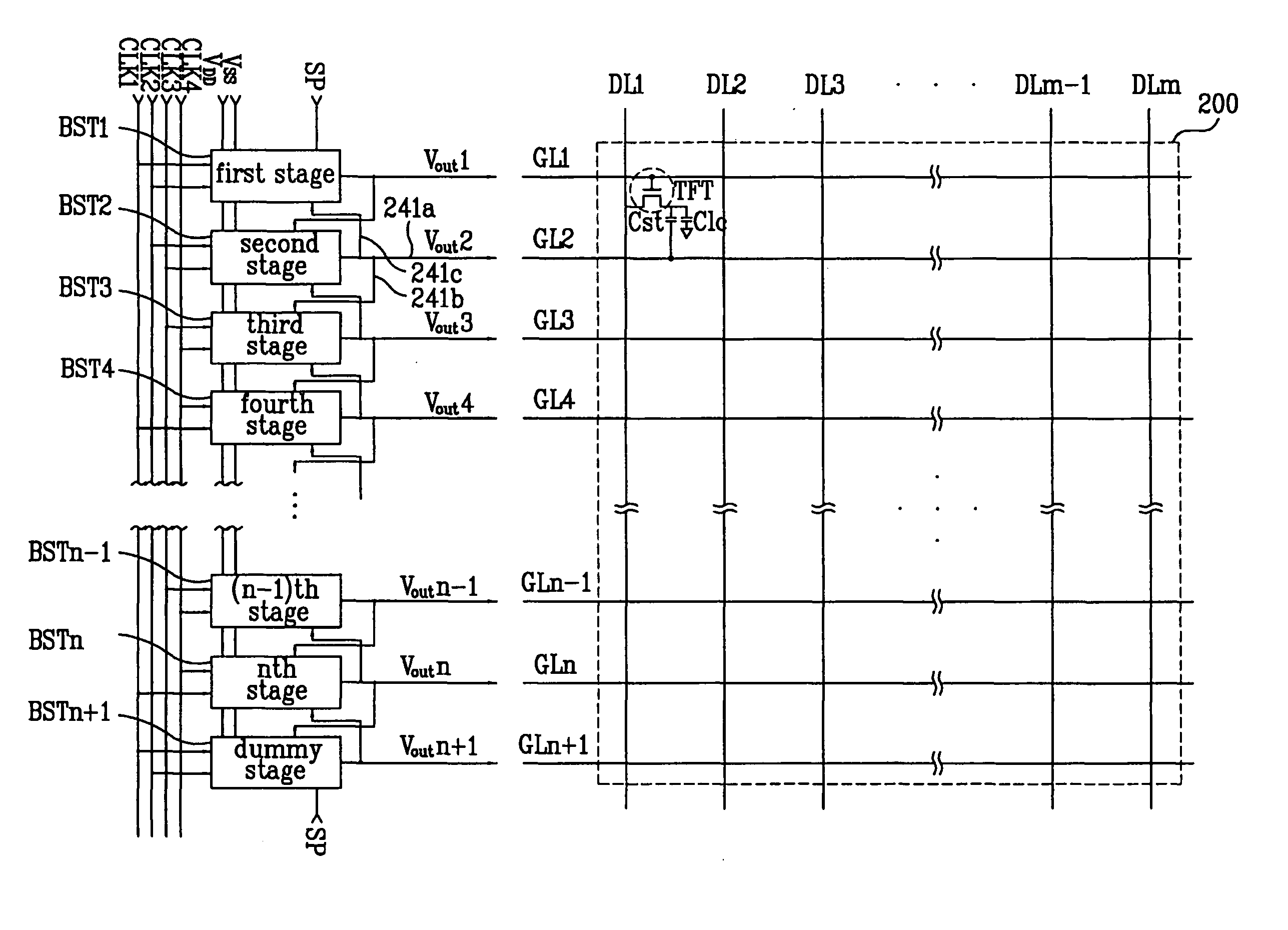
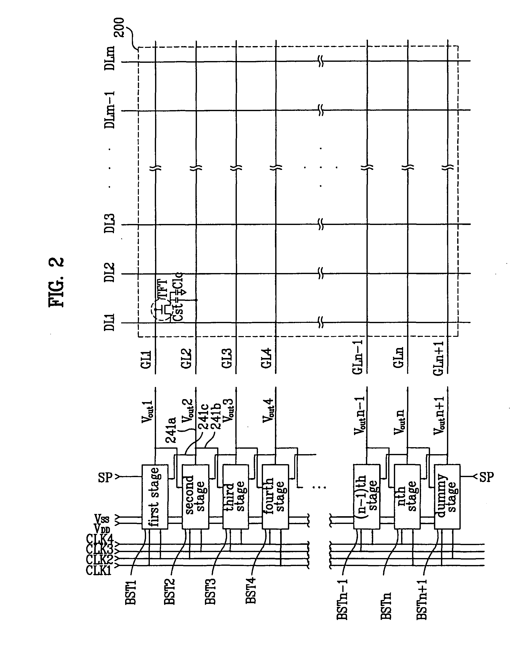
[0043]FIG. 2 shows a schematic diagram of an exemplary LCD device according to an embodiment of the present invention. Referring to FIG. 2, an LCD device includes an LCD panel 200, and a shift register. The LCD panel 200 is provided with a plurality of pixels PXL defined by a plurality of gate lines GL1 to GLn+1 and a plurality of data lines (DL1 to DLm). The shift register drives the plurality of gate lines GL1 to GLn+1 of the LCD panel 200.

[0044] The shift register is preferred to be built in the LCD panel 200 to decrease ...


PUM


Abstract

An LCD device includes a plurality of gate lines formed in an LCD panel; a plurality of driving stages, each of which sequentially outputting a respective enabling scan pulse to a corresponding one of the plurality of gate lines; at least one dummy stage responsive to an enabling scan pulse from a first one of the plurality of driving stages and supplying a disabling scan pulse to a second one of the plurality of driving stages to disable outputting of the enabling scan pulse; and a dummy gate line electrically connected to the at least one dummy stage.

Description

[0001] This application claims the benefit of Korean Patent Application No. 2005-57624, filed in Korea on Jun. 30, 2005, and No. 2006-21498, filed in Korea on Mar. 7, 2006, both of which are hereby incorporated by reference in their entirety. BACKGROUND OF THE INVENTION [0002] 1. Field of the Invention [0003] The present invention relates to a liquid crystal display (LCD) device, and more particularly, to a liquid crystal display (LCD) device having a shift register with increased lifetime. [0004] 2. Discussion of the Related Art [0005] In general, a liquid crystal display (LCD) device displays images by controlling light transmittance of liquid crystal. For this, the LCD device is provided with an LCD panel including a plurality of pixel regions arranged in a matrix, and a driving circuit for driving the LCD panel. [0006] The LCD panel includes a plurality of gate lines crossing a plurality of data lines to define a plurality of pixel regions. A thin film transistor (TFT) is provid...

Claims


Application Information

Patent Timeline
Patent Type & Authority Applications(United States)
IPC IPC(8): G09G3/36
CPCG09G3/3677G11C19/00G09G2330/027G09G2320/043
Inventor CHUN, MINPARK, KWONYOON, SOOMOON, TAE
Owner LG DISPLAY CO LTD
Why Eureka
Try Eureka