Air bubble trapping apparatus, liquid transporting apparatus, and ink-jet recording apparatus

Inactive Publication Date: 2007-01-04
BROTHER KOGYO KK
View PDF17 Cites 15 Cited by
  • Summary
  • Abstract
  • Description
  • Claims
  • Application Information

AI Technical Summary

Benefits of technology

[0030] According to the third aspect of the present invention, by trapping an air bubble in the ink on a surface of the electroconductive area by decreasing a difference between an electric potential of the electroconductive area and an electric potential of the ink at the time of recording, the air bubble can be prevented from flowing into the individual ink channel(s) and the common liquid chamber, and a variation in an amount of discharge of the ink, and in a speed of discharge of the ink can be reduced. Furthermore, by allowing an electrowetting phenomenon to occur by increasing the difference between the electric potential of the electroconductive area and the electric potential of the ink at the time of purging, the air bubble trapped on the surface of an electroconductive material can be removed. Thus, the bubble can hardly remain on the surface of the electroconductive material after purging, and the clog-up of the filter by the air bubble is prevented.
[0031] In the ink-jet recording apparatus of the present invention, the filter may further include an insulating layer which covers the electroconductive area of the substrate. When a layer, of which surface has a low wettability is used as the insulating layer, then when the difference between the electric potential of the electroconductive area and the electric potential of the ink is made to be small, the air bubble in the ink can be trapped assuredly on the surface of the insulating layer. Further, when a predetermined voltage is applied between the electroconductive area and the liquid, due to the electrowetting phenomenon which will be described later, the wettability of a part or portion of the surface of the insulating layer covering the electroconductive area to which the voltage is applied is increased. Therefore, the adhered air bubble can be released assuredly. Furthermore, by covering the electroconductive area by the insulating layer, when a predetermined voltage is applied between the electroconductive area and the liquid, an electric current flowing between the electroconductive area and the liquid can be reduced. Consequently, power consumption can be suppressed, and the voltage applied to the electroconductive area can be increased.
[0032] Further, the ink-jet recording apparatus of the present invention may further include a mode setting unit which is selectively settable to an air bubble trapping mode for trapping an air bubble in the ink on a surface of t

Problems solved by technology

Accordingly, there is a fear that the air bubble ca

Method used


Image

  • Air bubble trapping apparatus, liquid transporting apparatus, and ink-jet recording apparatus
  • Air bubble trapping apparatus, liquid transporting apparatus, and ink-jet recording apparatus
  • Air bubble trapping apparatus, liquid transporting apparatus, and ink-jet recording apparatus

Examples


first modified embodiment

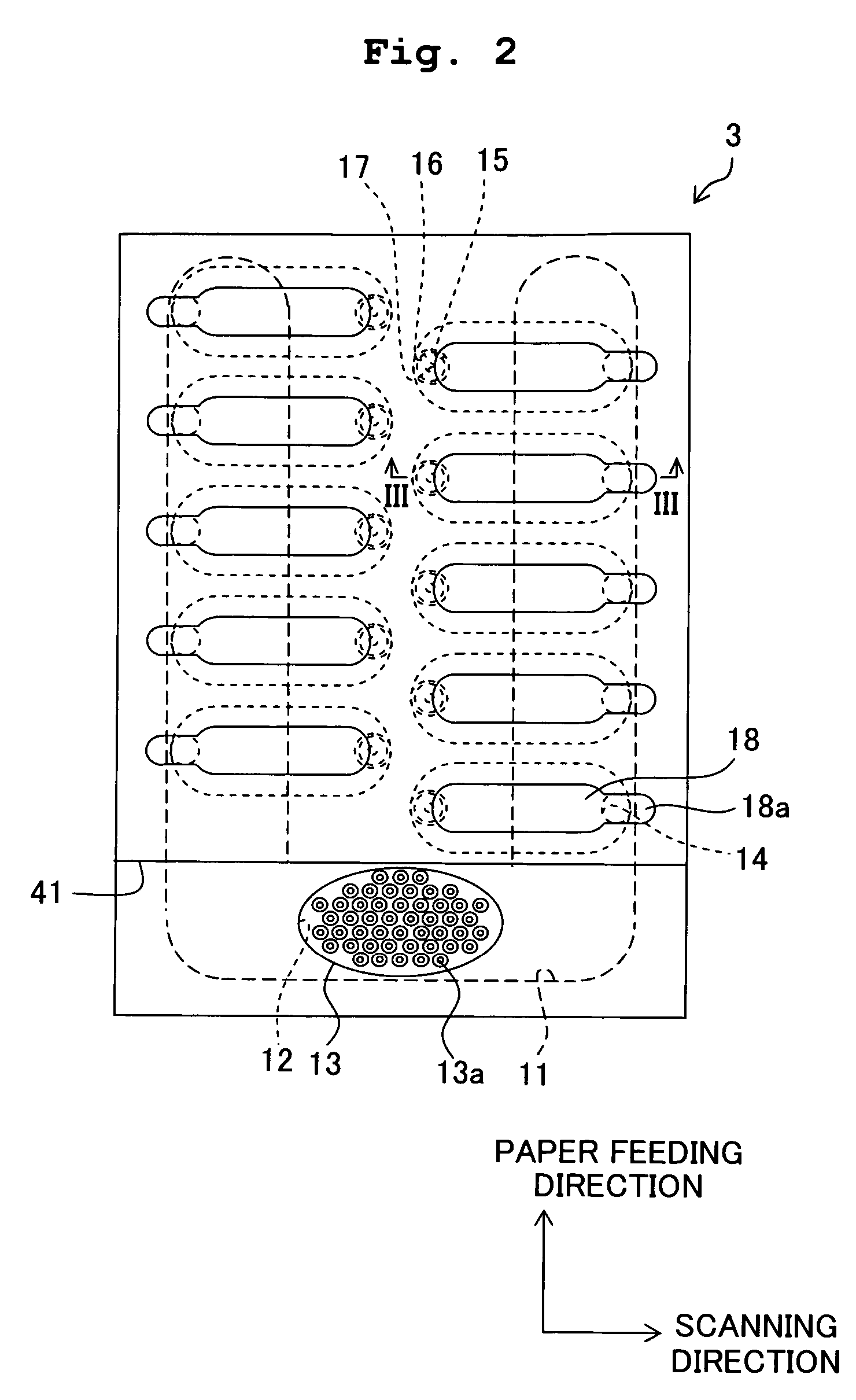
[0086] The filter is not limited to a filter in which an insulating layer is formed on a surface of an electroconductive substrate formed with a plurality of through holes. As shown in FIG. 9, a filter 71 may include an insulating member 72 in which a plurality of through holes 71a are formed, electrodes 73 which are made of a metallic material and each of which is formed on a surface of the insulating member 72 on a side opposite to the manifold channel 11, and on an inner surface which defines one of the through holes 71a, and an insulating layer 74 which is formed on surfaces of the electrodes 73. Here, the insulating member 72 and the insulating layer 74 are formed of an insulating material such as a fluororesin. However, the insulating member 72 and the insulating layer 74 may be formed of a same material or may be formed of different materials. Further, the electrodes 73 are connected to the driver IC 60 by a wiring which is not shown in the diagram.

[0087] In this case also, ...

second modified embodiment

[0088] Further, as in a filter 81 shown in FIG. 10, electrodes 82 may be formed on a surface of the insulating member 72 which is flat, the surface being on the side of the manifold channel 11, and an insulating layer 83 may be formed to cover the entire insulating member 72 from the upper side. In this case, since the surface on which the electrodes 82 are formed is a flat surface, the electrodes 82 can be formed easily.

third modified embodiment

[0089] Any insulating layer may not be formed on surfaces of the electrodes of the filter. For example, a filter 91a shown in FIG. 11A includes an electroconductive substrate 93a in which a plurality of through holes 92a is formed. Further, the electroconductive substrate 93a also serves as an electrode 94a. Here, the filter 91a has a same structure as the structure of the filter 13 in the embodiment, except that no insulating layer is formed on the surface of the filter 91a. Or, a filter 91b shown in FIG. 11B includes a substrate 93b which is electroconductive and in which a plurality of through holes 92b are formed; and electrodes 94b made of a metallic material and each formed on an inner surface of the substrate 93b which defines (forms) one of the through holes 92b, and on a surface of the substrate 93b. Here, the filter 91b has a structure similar to the structure of the filter 71 in the first modified embodiment except that no insulating layer is formed on surfaces of the ele...


PUM


Abstract

An air babble trapping apparatus which traps an air bubble in ink includes: a filter having through holes formed in the substrate and an insulating layer with a low wettability formed in a surface of the substrate; and an electric potential control unit which controls an electric potential difference between the electroconductive substrate and the ink. When the electric potential difference is set to be zero, the air bubble in the ink is adhered to a surface of the filter because of the low wettability of the insulating layer. When the electric potential difference is set to be a predetermined value, the air bubble adhered to the surface of the filter is released since the wettability of the surface of the insulating layer of the filter is increased due to an electrowetting phenomenon.

Description

CROSS REFERENCE TO RELATED APPLICATION [0001] The present application claims priority from Japanese Patent Application No. 2005-190495, filed on Jun. 29, 2005, the disclosure of which is incorporated herein by reference in its entirety. BACKGROUND OF THE INVENTION [0002] 1. Field of the Invention [0003] The present invention relates to an air bubble trapping apparatus which traps an air bubble in a liquid, a liquid transporting apparatus which includes the air bubble trapping apparatus and which transports the liquid, and an ink-jet recording apparatus which records an image etc. on a recording medium by discharging ink from a nozzle onto the recording medium. [0004] 2. Description of the Related Art [0005] Among ink-jet recording apparatuses in which a pressure is applied to an ink in a pressure chamber which communicates with a nozzle, and an image and / or a character are recorded on a recording medium by discharging the ink from the nozzle onto the recording medium, there are ink-...

Claims


Application Information

Patent Timeline
IPC IPC(8): B41J2/19B05B7/06
CPCB41J2/14233B41J2/17509B41J2002/14403B41J2002/14266B41J2/19
Inventor SUGAHARA, HIROTO
Owner BROTHER KOGYO KK
Why Eureka
Try Eureka