A Raman probe
assembly for analyzing a specimen, comprising: a
light source for generating
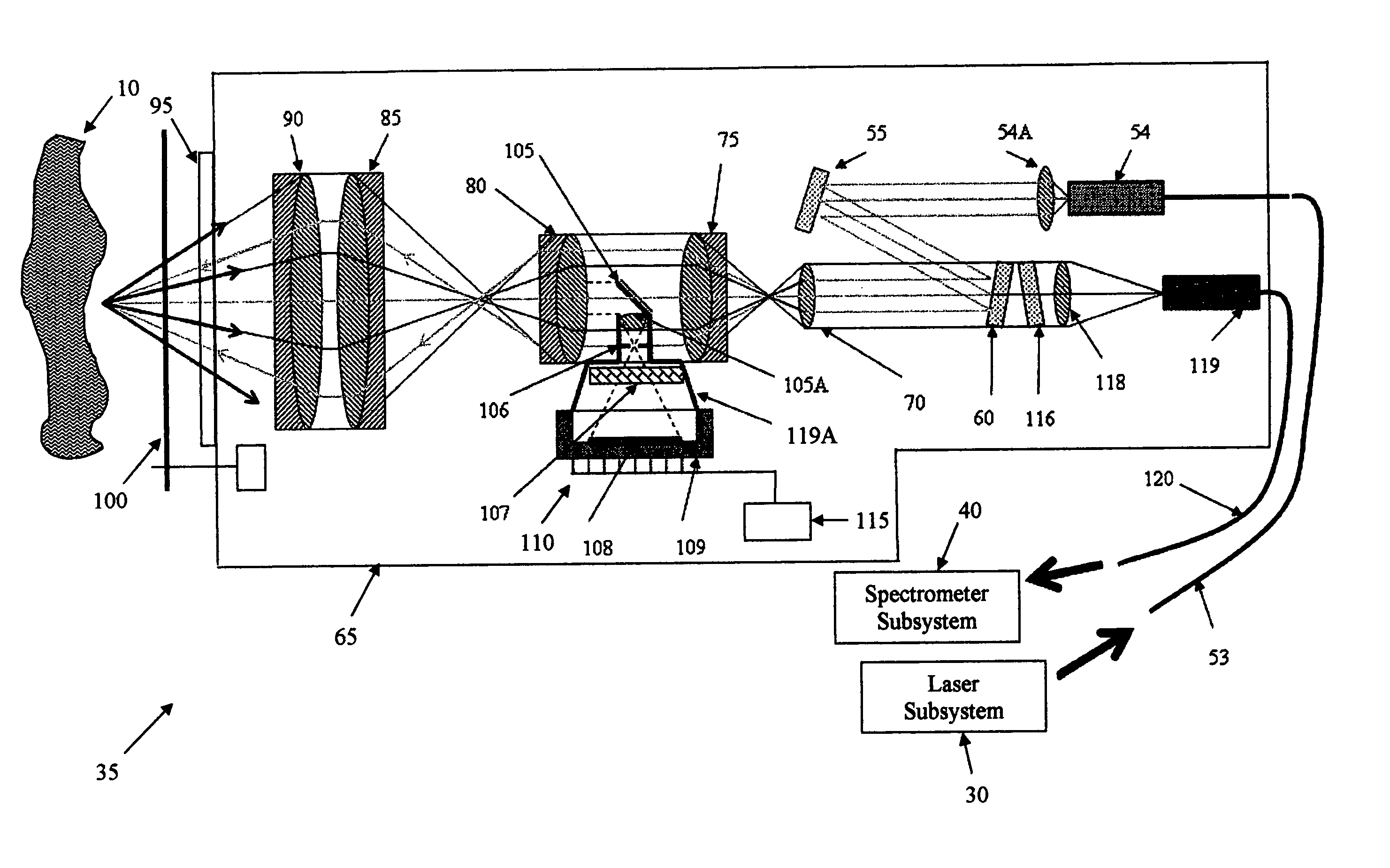
laser excitation light; a camera for capturing an image; a light analyzer for analyzing a Raman signature; and a light path for (i) delivering the
laser excitation light from the
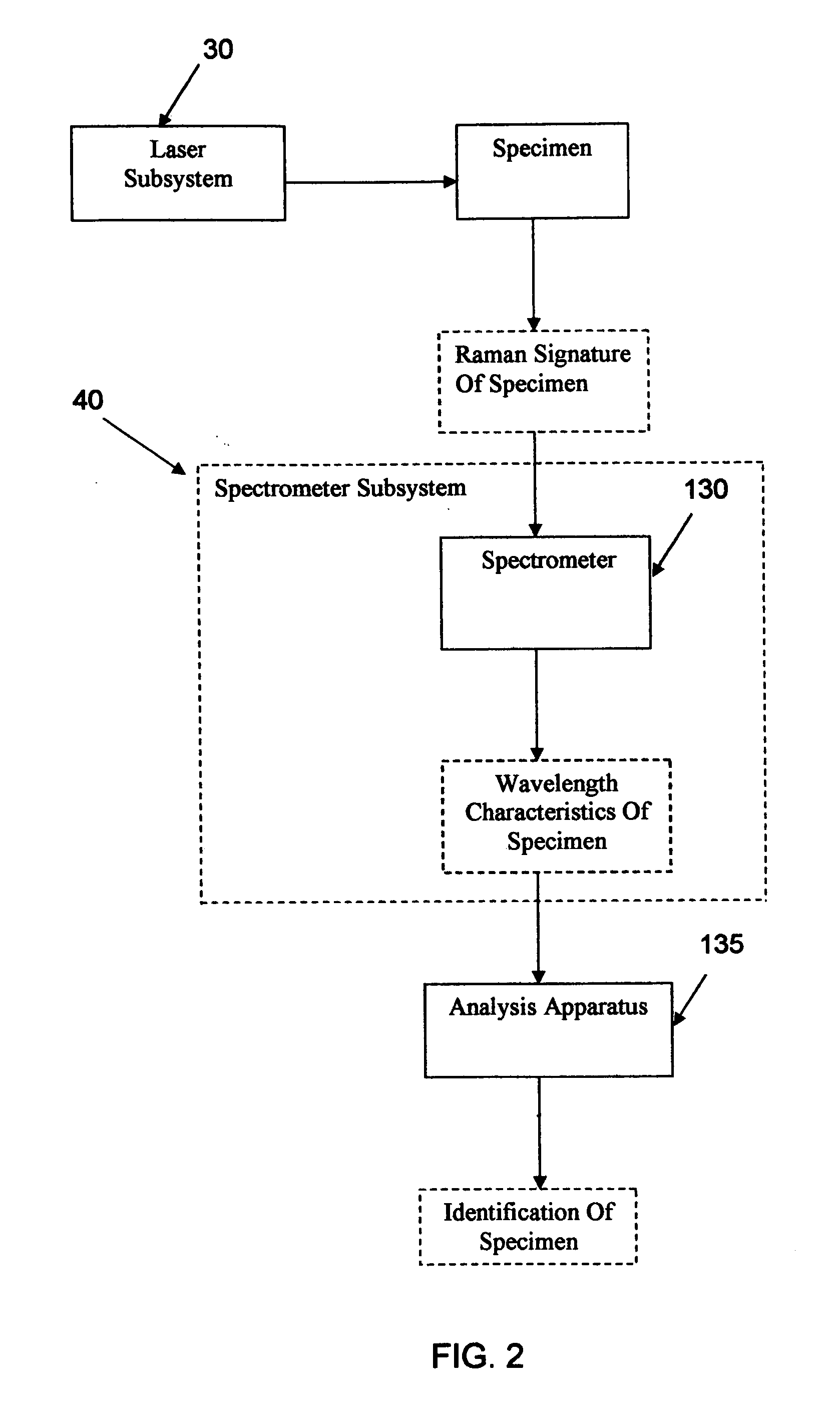
light source to the specimen so as to produce the Raman signature for the specimen, (ii) capturing an image of the specimen and directing that image to the camera, and (iii) directing the Raman signature of the specimen to the light analyzer. A Raman probe
assembly for analyzing a specimen, comprising: a
light source for generating
laser excitation light; a camera for capturing an image; a light analyzer for analyzing a Raman signature; a
first light path for delivering the laser excitation light from the light source to the specimen so as to produce the Raman signature for the specimen; a second light path for capturing an image of the specimen and directing that image to the camera; a third light path for directing the Raman signature of the specimen to the light analyzer; wherein the a least a portion of the
first light path, the second light path and the third light path are coaxial with one another. A Raman probe
assembly for analyzing a specimen, comprising: a light source for generating laser excitation light; a light analyzer for analyzing a Raman signature; a light path for (i) delivering the laser excitation light from the light source to the specimen so as to produce the Raman signature for the specimen, and (ii) directing the Raman signature of the specimen to the light analyzer; wherein the assembly further comprises a probe body for housing the at least a portion of the light path, and a window, with the light path extending through the window; and further wherein the probe body further comprises a
shutter / wiper disposed adjacent to the window. A Raman probe assembly for analyzing a specimen, comprising: a light source for generating laser excitation light; a light analyzer for analyzing a Raman signature; a light path for (i) delivering the laser excitation light from the light source to the specimen so as to produce the Raman signature for the specimen, and (ii) directing the Raman signature of the specimen to the light analyzer; and wherein the light analyzer comprises a
transmitter for transmitting information using an Internet Web protocol. A method for identifying the nature of a specimen, the method comprising: providing a Raman probe assembly comprising: a light source for generating laser excitation light; a camera for capturing an image; a light analyzer for analyzing a Raman signature; a light path for (i) delivering the laser excitation light from the light source to the specimen so as to produce the Raman signature for the specimen, (ii) capturing an image of the specimen and directing that image to the camera, and (iii) directing the Raman signature of the specimen to the light analyzer wherein the assembly further comprises a probe body for housing the at least a portion of the light path, and a window, with the light path extending through the window; wherein the probe body further comprises a
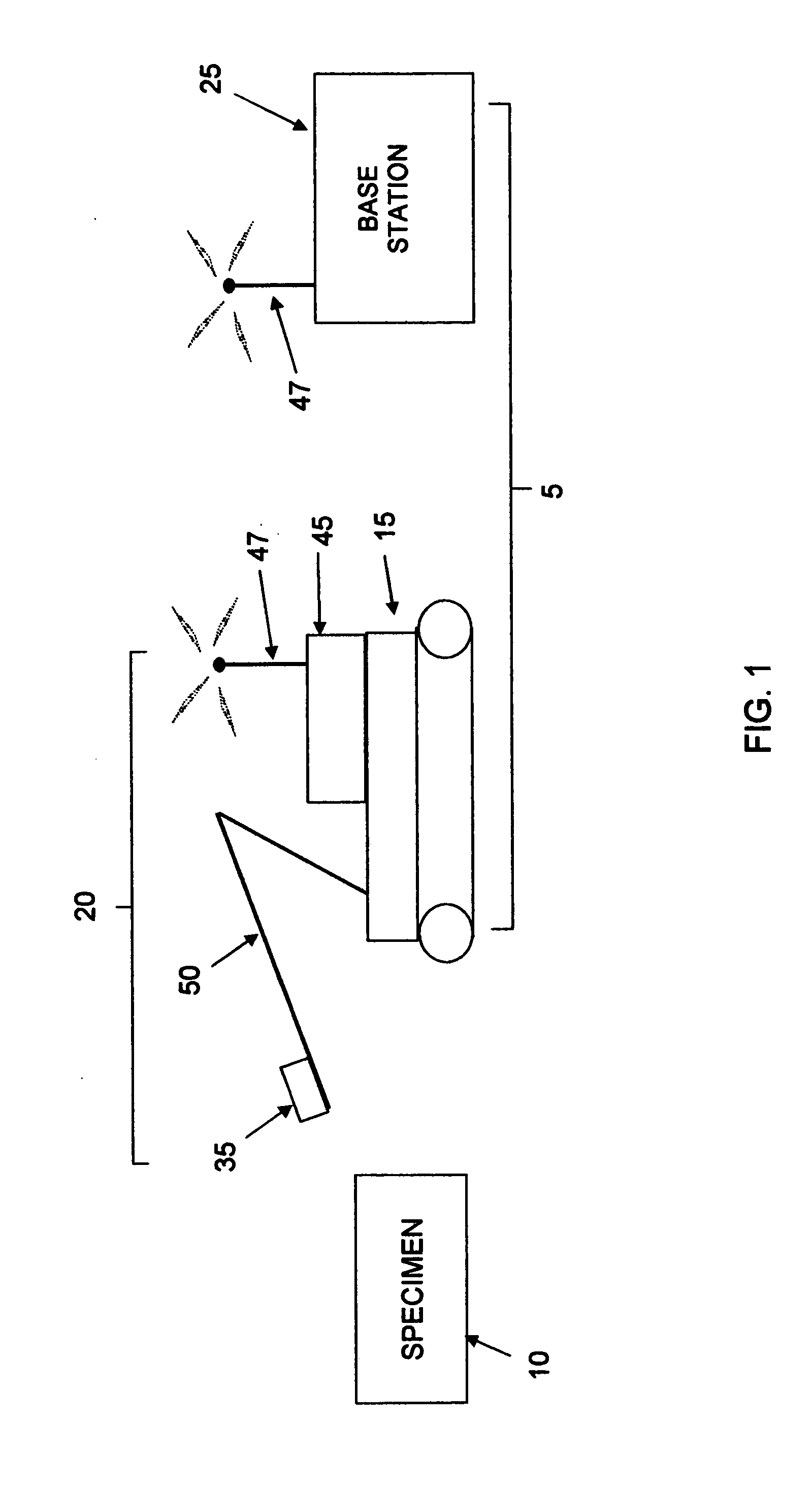
shutter / wiper disposed adjacent to the window; wherein the assembly is carried by a remote controlled
robot; providing a
base station for receiving the image, and for remotely controlling the
robot, and for receiving information from the light analyzer; navigating the
remote control robot from the
base station to a position adjacent to the specimen; opening the
shutter / wiper; using the camera to aim the probe body at the specimen; energizing the light source so that the laser excitation light is directed at the specimen; and analyzing the return light passed to the light analyzer so as to determine of the nature of the specimen.

