
Medical monitoring data collection and remote control module and method

Inactive Publication Date: 2007-01-04
KASPRZYK MARLON Z +1
View PDF21 Cites 70 Cited by
  • Summary
  • Abstract
  • Description
  • Claims
  • Application Information

AI Technical Summary

Benefits of technology

[0008] An interface system for communication between a medical monitoring apparatus or system and a remote base station, using an established wireless network, is provided. The system comprises a data collection module configured to receive data relating to a characteristic of the medical monitoring apparatus. The data collection module comprises a port connected to the module for coupling the module to a portable communication device, wherein the portable communication device i

Problems solved by technology

Those devices are infrequent in the consumer market, however, because the cost of their manufacture, and subsequent sale price, are prohibitively high for the average consumer.
Most personal communication devices, however, do not allow for the receipt of an open “data call”, i.e., a request for an open data connection from a remote location.
As a consequence, most portable communication devices cannot be used to establish an on-demand data connection with a remote location.
It is therefore not currently possible to use such devices as a means for the transfer of data from a remote source.
Parties seeking a cost-effective means to remotely monitor and control equipment and devices are therefore unable to turn to existing portable communication devices or their networks as a solution.
Instead, such parties must turn to the more expensive satellite control systems, or other more expensive proprietary control systems, including the egregiously expensive modification of an existing cellular phone network as described in U.S. Patent Application Publication No. 2002 / 0077114.

Method used


Image

  • Medical monitoring data collection and remote control module and method
  • Medical monitoring data collection and remote control module and method
  • Medical monitoring data collection and remote control module and method

Examples


Embodiment Construction

[0028] While this invention is susceptible of embodiments in many different forms, there is shown in the drawings and will herein be described in detail preferred embodiments of the invention with the understanding that the present disclosure is to be considered as an exemplification of the principles of the invention and is not intended to limit the broad aspect of the invention to the embodiments illustrated.

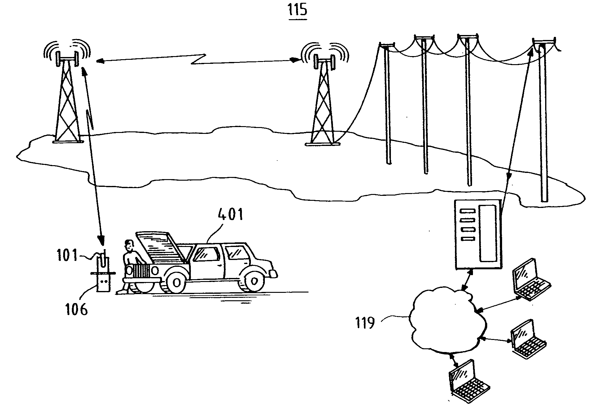
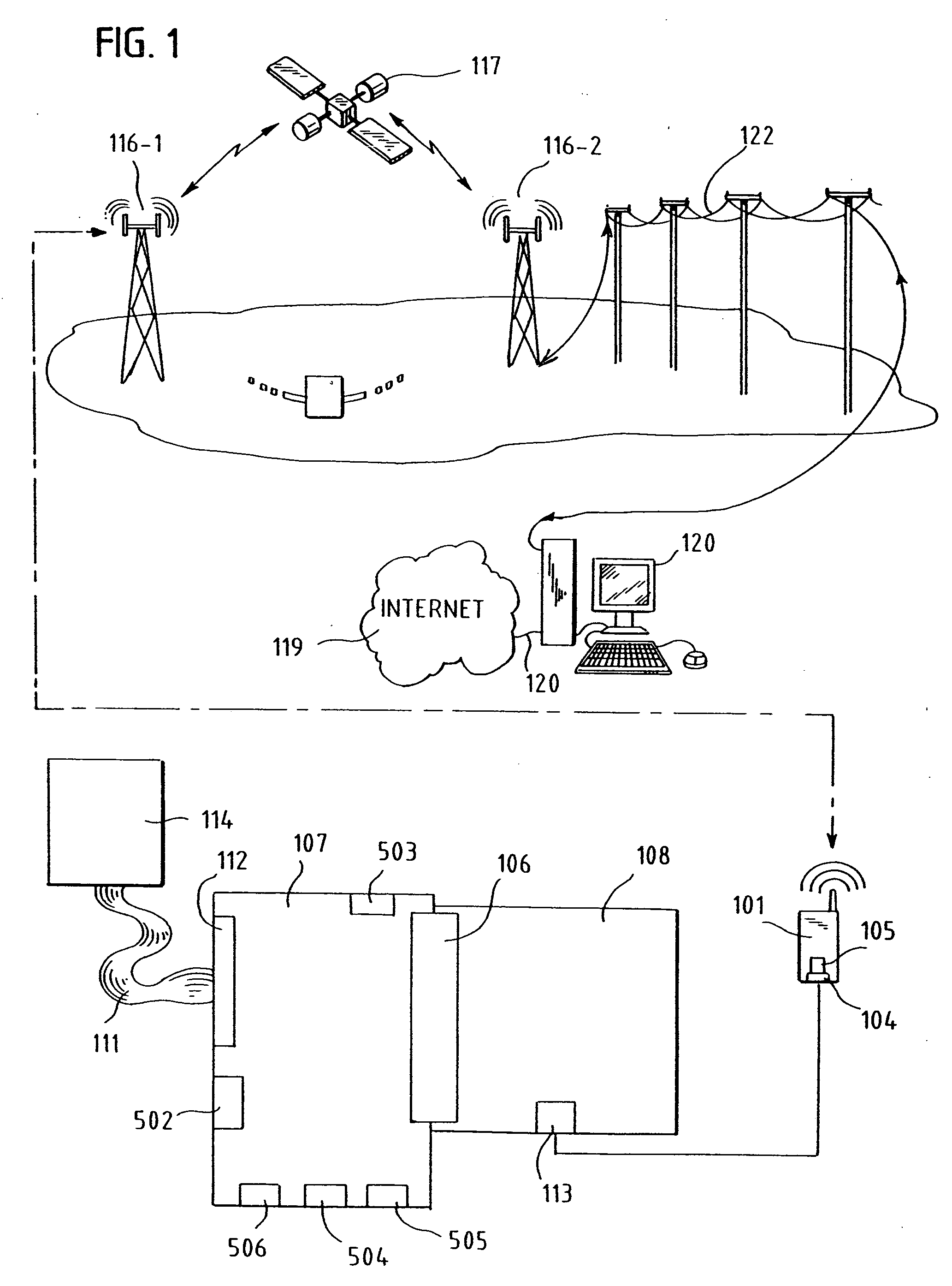
[0029] Referring initially to FIG. 1, there is illustrated an overview diagram for an interface system for communication between an apparatus 114 and a remote base station 121 over an established wireless network 115. The interface system includes a data collection module 107 which is configured to receive data relating to a characteristic of the apparatus 114. A port 106 is connected to the data collection module 107 for coupling the data collection module 107 to a portable communication device 101 configured for wireless communication over the established wireless network 1...


PUM


Abstract

An interface system and method are provided for communication between a medical monitoring apparatus designed to be worn by a patient and a remote base station using an established wireless network. The system comprises a data collection module configured to receive data relating to the medical monitoring apparatus. The data collection module comprises a port connected to the data collection module for coupling the data collection module to a portable communication device configured for wireless communication over the established wireless network. The data collection module further comprises a controller configured to transmit a message in response to the received data, wherein the message is transmitted to the remote base station via the port and the portable communication device. The controller can also be used to control aspects of the medical monitoring apparatus in response to instructions received from the remote base station via the portable communication device and the established wireless network.

Description

CROSS-REFERENCE TO RELATED APPLICATIONS [0001] This application is a continuation-in-part to and claims the benefit of U.S. patent application Ser. No. 11 / 235,043, filed Sep. 26, 2005, entitled “DATA COLLECTION AND REMOTE CONTROL MODULE AND METHOD” which is incorporated herein by reference and made a part hereof. Ser. No. 11 / 235,043 claims the benefit of U.S. Provisional Application No. 60 / 696,351 filed on Jul. 1, 2005, the contents of which are also incorporated herein by reference and made a part hereof.TECHNICAL FIELD [0002] The invention generally relates to a real-time medical monitoring data collection and remote control monitoring and data collection module and to a method of using the module. More particularly, the invention relates to an interface system for communication between a medical monitoring apparatus and a remote base station using an established wireless network. BACKGROUND OF THE INVENTION [0003] Portable communication devices are widely known and popular in the...

Claims


Application Information

Patent Timeline
IPC IPC(8): H04Q7/00G16Z99/00H04W24/00H04W88/04H04W92/10
CPCA61B5/021A61B5/14532A61B5/4839A61B5/0022H04W88/04H04W92/10H04W24/00G16H40/67G16Z99/00
Inventor KASPRZYK, MARLON Z.WARDAWY, KAZIMIERZ G.
Owner KASPRZYK MARLON Z
Learn More