Systems and methods for reducing drag and/or vortex induced vibration

a technology of vortex and reducing structure, applied in the direction of drilling pipes, mechanical equipment, artificial islands, etc., can solve the problems of excessive vortex-induced vibration of the hull of the spar production facility, and the structure can be subject to greater drag force, so as to reduce the drag and/or vortex induced vibration of the structur

Inactive Publication Date: 2007-01-04
SHELL OIL CO
View PDF34 Cites 24 Cited by
  • Summary
  • Abstract
  • Description
  • Claims
  • Application Information

AI Technical Summary

Benefits of technology

[0021] One aspect of invention provides a system for reducing drag and / or vortex induced vibration of a structure, the system comprising a fairing defining a plurality of perforations, wherein the fairing is suitable for placement around the structure, the perforations defining a porosity of the fairing of at least 1%.

Problems solved by technology

These vibrations may be caused by oscillating dynamic forces on the surface, which can cause substantial vibrations of the structure, especially if the forcing frequency is at or near a structural natural frequency.
The hulls of spar production facilities, therefore, can be exposed to excessive vortex-induced vibrations.
It is noted that even moderate velocity currents in flowing fluid environments acting on linear structures can cause stresses.
Drilling in ever deeper water depths requires longer riser pipe strings which, because of their increased length and subsequent greater surface area, may be subject to greater drag forces which must be resisted by more tension.
Accordingly, the adverse effects of drag forces against a riser or other structure caused by strong and shifting currents in these deeper waters increase and set up stresses in the structure which can lead to severe fatigue and / or failure of the structure if left unchecked.
If the frequency of this harmonic load is near the resonant frequency of the structure, large vibrations transverse to the current can occur.
These vibrations can, depending on the stiffness and the strength of the structure and any welds, lead to unacceptably short fatigue lives.
In fact, stresses caused by high current conditions in marine environments have been known to cause structures such as risers to break apart and fall to the ocean floor.
For instance, a riser pipe that is vibrating due to vortex shedding will generally disrupt the flow of water around it more than a stationary riser.
This may result in more energy transfer from the current to the riser, and hence more drag.
Likewise, elongated structures with excessive VIV and / or drag forces that extend far above the ground can be difficult, expensive and dangerous to reach by human workers to install VIV and / or drag reduction devices.
In addition, fairings may cause the boundary layer to separate, which may cause increased drag and / or increased VIV.
In addition, fairings may hinder the effectiveness of a cathodic protection system of a tubular.
In addition, fairings may have a large mass, and be difficult to transport and / or install.

Method used


Image

  • Systems and methods for reducing drag and/or vortex induced vibration
  • Systems and methods for reducing drag and/or vortex induced vibration
  • Systems and methods for reducing drag and/or vortex induced vibration

Examples


Embodiment Construction

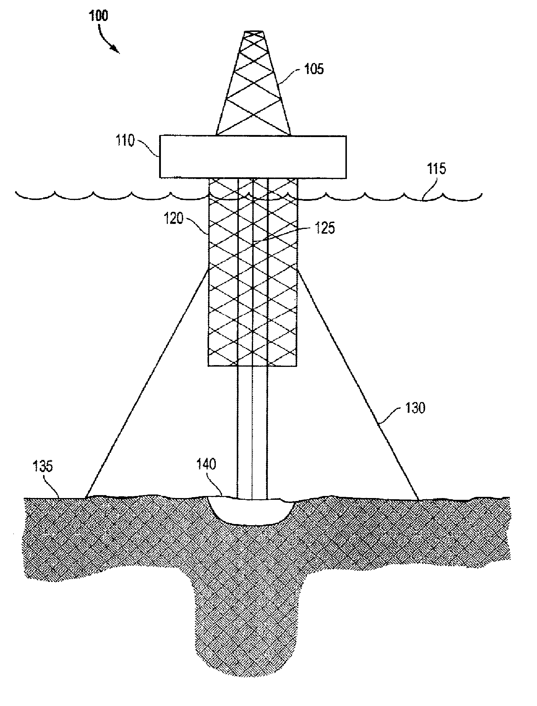
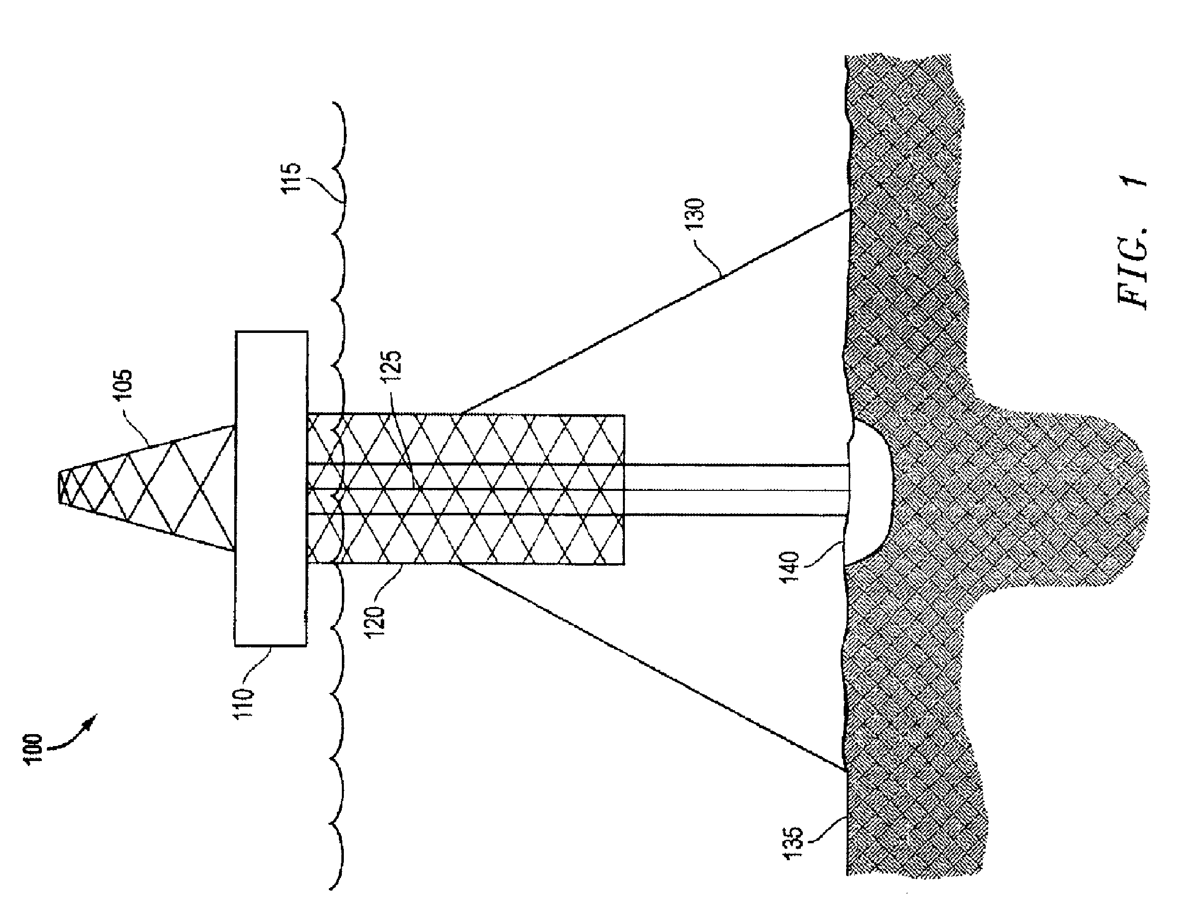
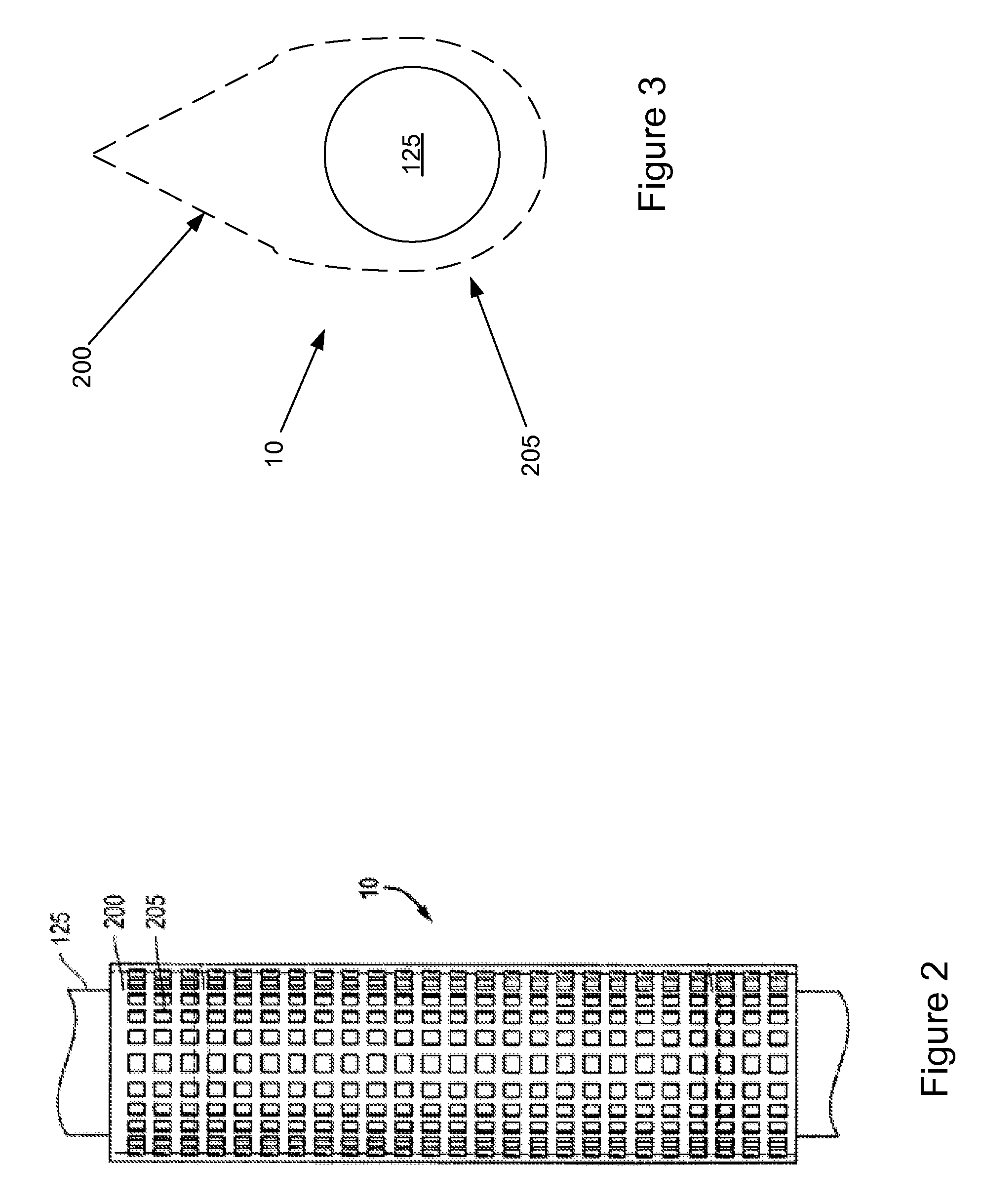
[0034] In one embodiment, there is disclosed a system for reducing drag and / or vortex induced vibration of a structure, the system comprising a fairing defining a plurality of perforations, wherein the fairing is suitable for placement around the structure, the perforations defining a porosity of the fairing of at least 1%. In some embodiments, the fairing comprises a porosity from 2% to 80%, or from 5% to 70%, or from 10% to 60 %. In some embodiments, the fairing comprises a front and a tail, wherein the perforations comprise at least one centered perforation at the front, and at least one perforation at the tail. In some embodiments, the fairing comprises a front and a tail, wherein the perforations comprise at least two off-centered perforations at the front, and at least one perforation at the tail. In some embodiments, the fairing comprises a front and a tail, wherein the perforations provide a fluid path within the fairing from the front to the tail and around the structure, w...


PUM


Abstract

There is disclosed a system for reducing drag and/or vortex induced vibration of a structure, the system comprising a fairing defining a plurality of perforations, wherein the fairing is suitable for placement around the structure, the perforations defining a porosity of the fairing of at least 1%.

Description

CROSS-REFERENCE TO RELATED APPLICATION [0001] The present application claims the benefit of the filing date of U.S. Provisional patent application Ser. No. 60 / 690,973, filed on Jun. 16, 2005, the disclosure of which is incorporated herein by reference.FIELD OF THE INVENTION [0002] The present invention relates to systems and methods for reducing drag and / or vortex-induced vibration (“VIV”). DESCRIPTION OF THE RELATED ART [0003] Whenever a bluff body, such as a cylinder, experiences a current in a flowing fluid environment, it is possible for the body to experience vortex-induced vibration (VIV). These vibrations may be caused by oscillating dynamic forces on the surface, which can cause substantial vibrations of the structure, especially if the forcing frequency is at or near a structural natural frequency. [0004] Drilling for and / or producing hydrocarbons or the like from subterranean deposits which exist under a body of water exposes underwater drilling and production equipment to...

Claims


Application Information

Patent Timeline
Patent Type & Authority Applications(United States)
IPC IPC(8): E02D5/60
CPCE02D27/52E02B17/00E02D5/60E21B17/01F15D1/10
Inventor ALLEN, DONALD WAYNELEE, LIMENON, RAGHUNATH GOPALWORTHEN, RACHEL ANNA
Owner SHELL OIL CO
Why Eureka
Try Eureka