Apparatus for fabricating fiber reinforced plastic parts

a technology of fiber reinforced plastic parts and apparatuses, applied in the direction of manufacturing tools, coatings, ceramic shaping apparatus, etc., can solve the problems of requiring 6 months to complete, using expensive forms or molds, and the probable cost of a 45 foot hull could easily exceed $500,000.00, so as to achieve fast and cost-effective

Inactive Publication Date: 2007-01-04
SCHROEDER ERNEST C
View PDF10 Cites 177 Cited by
  • Summary
  • Abstract
  • Description
  • Claims
  • Application Information

AI Technical Summary

Benefits of technology

[0011] It is an object of a preferred embodiment of the present invention to provide a fast, cost-effective apparatus and method for fabricating FRP parts directly from computer drawing data without the need for costly molds or other intermediate forming tools.
[0012] It is another of a preferred embodiment of the present invention to provide a method for fabricating FRP parts that avoids the costs of traditional molds, such as mold maintenance, mold storage, and security.
[0013] It is another object of a preferred embodiment of the present invention to provide an apparatus and method for developing a FRP laminated shape that is self-supporting and inherently strong without part-specific tooling.

Problems solved by technology

Typically these parts must be made using expensive forms or molds.
Using current technology, the probable cost for a 45 foot hull could easily exceed $500,000.00 and require 6 months to complete depending upon the degree of accuracy and finish desired.
There is no process known to exist that can create a large FRP shape in space that is dimensionally accurate, and possesses structural integrity.

Method used


Image

  • Apparatus for fabricating fiber reinforced plastic parts
  • Apparatus for fabricating fiber reinforced plastic parts
  • Apparatus for fabricating fiber reinforced plastic parts

Examples


Embodiment Construction

Apparatus of the Present Invention

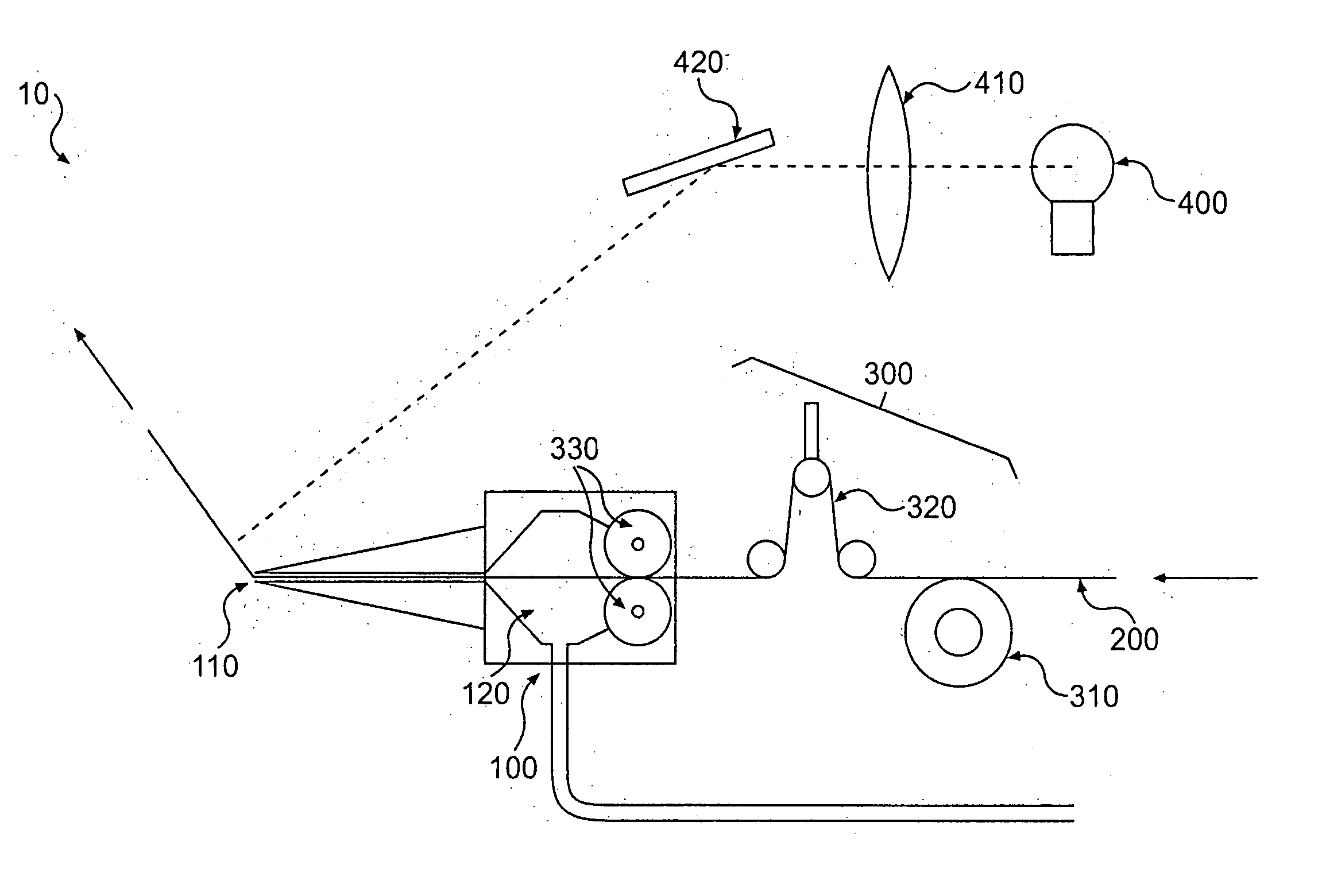
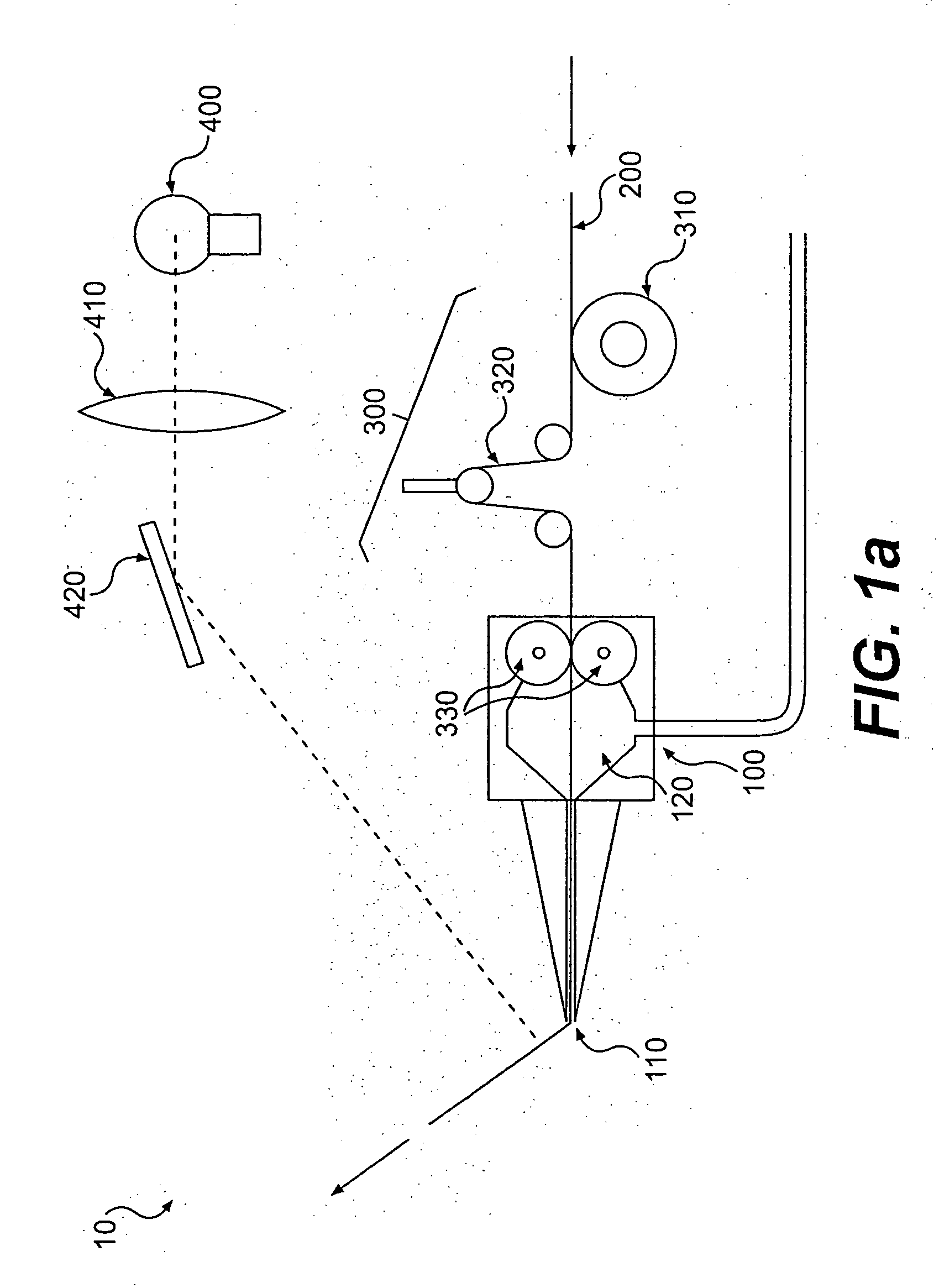
[0035] Reference will now be made in detail to a preferred embodiment of the present invention. The apparatus for fabricating fiber reinforced plastic parts comprises: an extrusion head, wherein the extrusion head further comprises an orifice; means for moving the head in a controlled pattern; means for regulating the speed of extrusion from the extrusion head; a resin impregnator; a supply of fiber reinforcement, wherein the fiber reinforcement passes through the impregnator and through the extrusion head; a supply of resin for impregnating the fiber reinforcement; means for feeding the fiber reinforcement to the extrusion head; means for impregnating the fiber reinforcement with the resin; a resin-curing radiation source; and a readable definition of the part.

[0036] A preferred embodiment of the apparatus 10 is shown in FIG. 1a. According to the preferred embodiment, an extrusion head 100 has an orifice 110 located therein through which resin im...


PUM

PropertyMeasurementUnit
wavelength rangeaaaaaaaaaa

Abstract

The invention relates to an apparatus and method for fabricating FRP parts. More specifically, the invention relates to a method for forming FRP parts without the use of forms or molds. According to a preferred embodiment of the present invention, the method for fabricating an FRP part comprises the steps of: programming a readable definition of a part into a machine, wherein the machine moves an extrusion head mounted to the machine in a controlled pattern; and wherein the machine regulates the speed of extrusion from the extrusion head; feeding a fiber reinforcement to the extrusion head of the machine; impregnating the fiber reinforcement with a radiation-initiated resin; extruding the impregnated fiber reinforcement from an orifice in the extrusion head; and exposing the extruded fiber reinforcement to curing radiation.

Description

CROSS-REFERENCE TO RELATED APPLICATIONS [0001] The present invention relates to, and is entitled to the benefit of the earlier filing date and priority of, U.S. Provisional Application No. 60 / 272,039, filed on Mar. 1, 2001.FIELD OF THE INVENTION [0002] The invention relates to an apparatus and method for fabricating fiber reinforced plastic parts. More specifically, the invention relates to an apparatus and method for forming fiber reinforced plastic (“FRP”) parts without the need for forms or molds. BACKGROUND OF THE INVENTION [0003] The use of fiber (primarily glass fiber) reinforced plastic (“FRP”) parts is widespread in many industries, including manufacturing, marine, aerospace, transportation, or any industry demanding molded, durable high strength, parts. FRP is a standard and understood name for fiberglass parts in the field of art and includes reinforcement materials other than fiberglass. Typically these parts must be made using expensive forms or molds. What is needed in ...

Claims


Application Information

Patent Timeline
Patent Type & Authority Applications(United States)
IPC IPC(8): B28B5/00B29C35/10B29C48/05B29C48/156B29C70/50
CPCB29C35/10B29C70/50B29C47/027B29C47/0014B29C48/05B29C48/156B33Y10/00
Inventor SCHROEDER, ERNEST C.
Owner SCHROEDER ERNEST C
Why Eureka
Try Eureka