Rotary connector device

a technology of rotary connectors and connectors, which is applied in the direction of current collectors, rotary current collectors, electrical appliances, etc., can solve the problems of noise and/or sliding sound of devices, and achieve the effect of reducing the number of components forming the slip ring mechanism

Inactive Publication Date: 2007-01-04
YAZAKI CORP
View PDF5 Cites 29 Cited by
  • Summary
  • Abstract
  • Description
  • Claims
  • Application Information

AI Technical Summary

Benefits of technology

[0005] Under the circumstances, it is therefore an object of the present invention to provide a rotary connector device that enables the number of components forming the slip ring mechanism to be reduced and also enables the slip ring mechanism to be installed in a narrow space in the axial direction and that can eliminate the use of an exclusive attachment portion like the brim part in installing the slip ring mechanism.

Problems solved by technology

Moreover, due to the arrangement of the slip ring mechanism between the stationary top face part of the stator and the rotary top face part of the rotor, both of which cover the upside of the cable chamber, the slip ring mechanism is not exposed to an outside of the rotary connector device, preventing an invasion of foreign particles into the device and an occurrence of noise and / or sliding sound from the device.

Method used


Image

  • Rotary connector device
  • Rotary connector device
  • Rotary connector device

Examples


Embodiment Construction

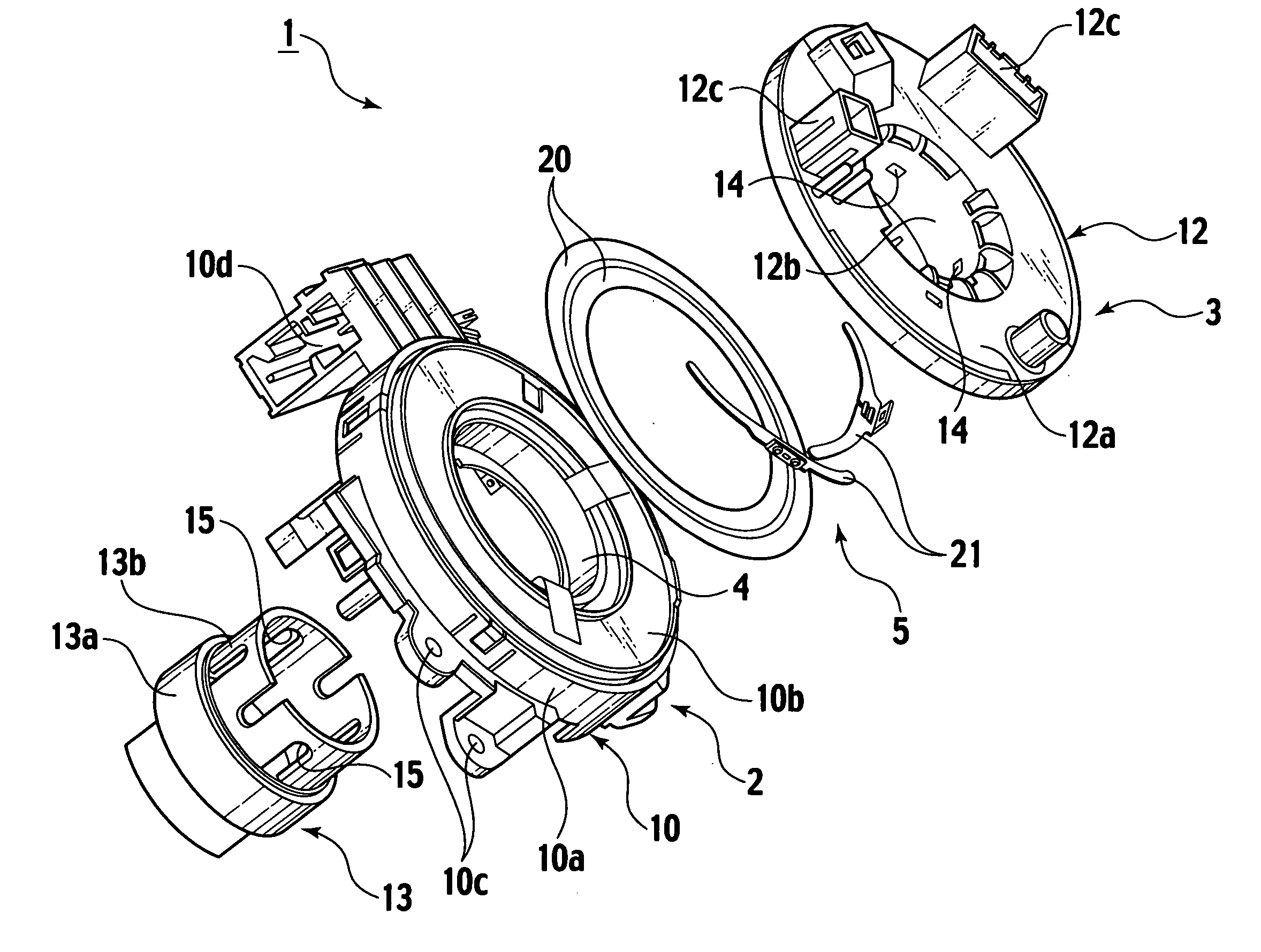
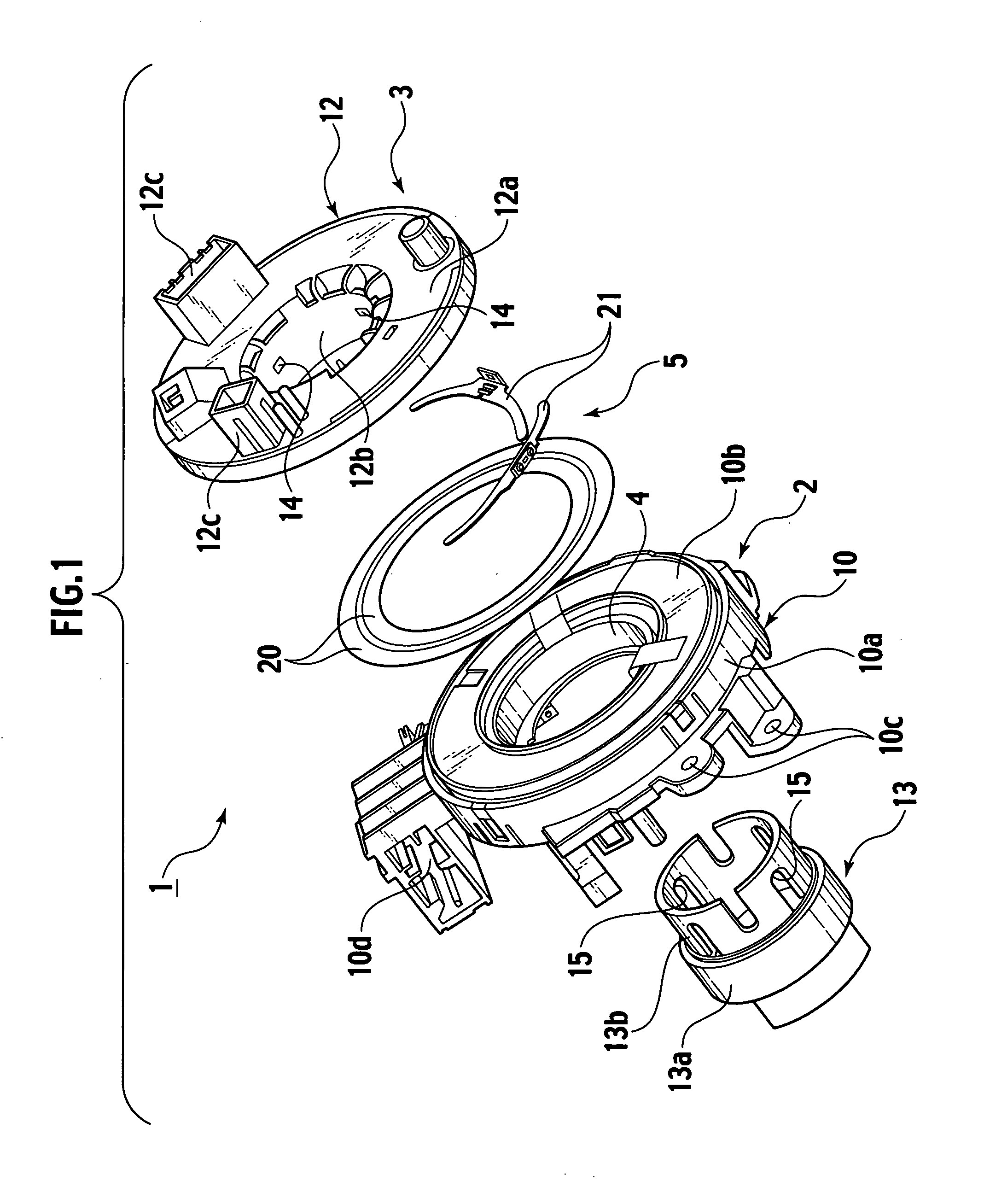
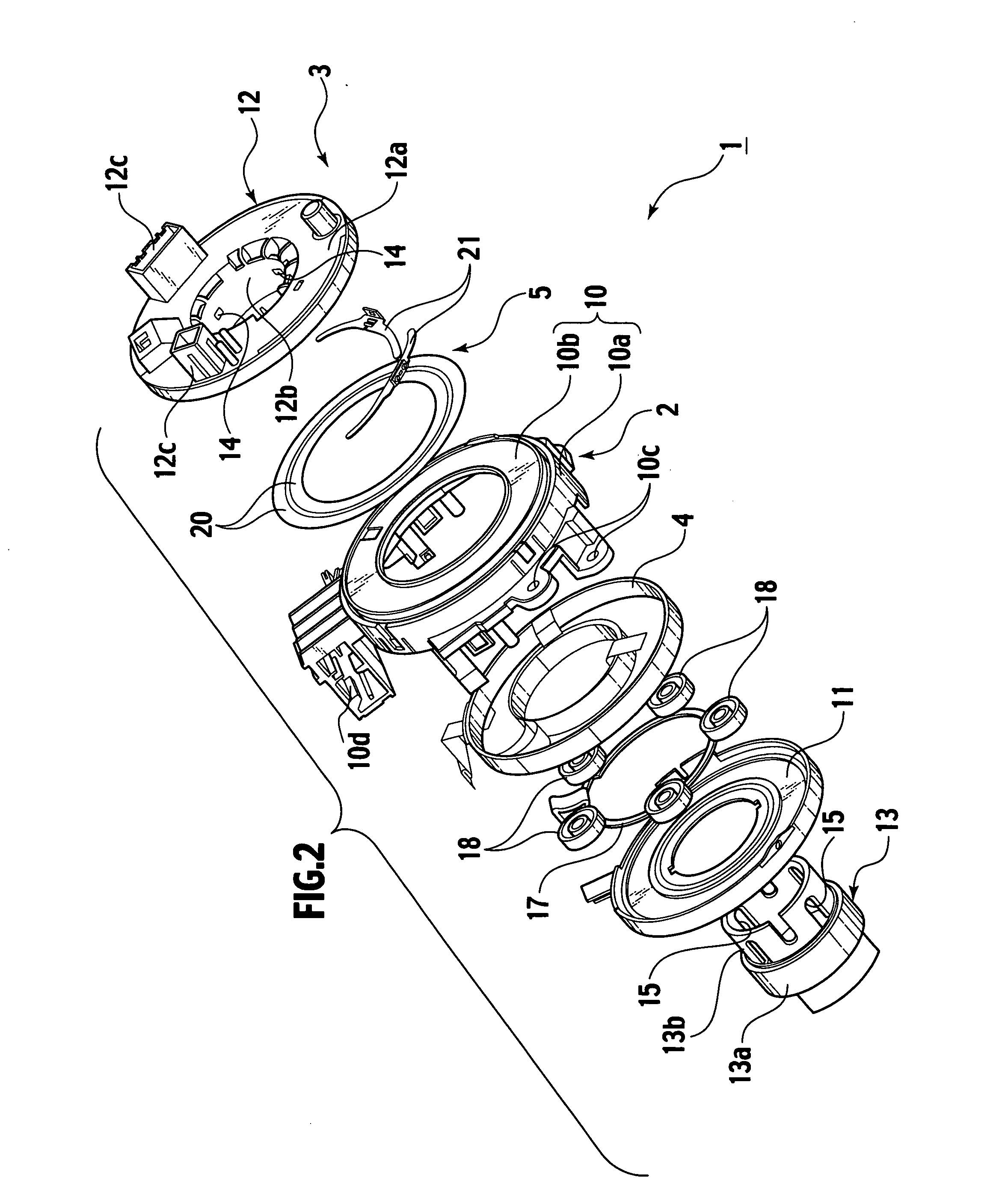
[0028] An embodiment of the present invention will be described with reference to the drawings. FIG. 1 shows one embodiment of the present invention. FIG. 1 is an exploded perspective view of a rotary connector device. FIG. 2 is an exploded perspective view of the rotary connector device, in which an interior of a stator is also exploded. FIG. 3 is a sectional view of the rotary connector device. FIG. 4 is an enlarged view of a part A of FIG. 3. FIG. 5 is a perspective view of an inner side of an upper rotating member having a sliding terminal attached thereto. FIG. 6 is a perspective view of the sliding terminal.

[0029] As shown in FIGS. 1 to 3, the rotary connector device 1 comprises a stator 2 fixed to a steering column (not shown), a rotor 3 fixed to the steering column and rotatably fitted in the stator 2, a flexible flat cable 4 for attaining an electrical connection between the rotor 3 and the stator 2 and a slip ring mechanism 5 for also attaining the electrical connection b...


PUM


Abstract

A rotary connector device includes a stator, a rotor rotatably fitted to the stator, a cable chamber surrounded by the stator and the rotor and also formed around a rotating center of the rotor circumferentially, a flexible flat cable accommodated in the cable chamber so as to allow rotating of the rotor in relation to the stator, the cable having one end led to the stator and another end led to the rotor, and a slip ring mechanism having two conductive rings fixed to the stator and two sliding terminals fixed to the rotor. The stator has a stationary top face part formed so as to cover an upside of the cable chamber, while the rotor has a rotary top face part formed so as to adjoin the stationary top face part of the stator. The slip ring mechanism is arranged in a clearance between the stationary top face part of the stator and the rotary top face part of the rotor.

Description

BACKGROUND OF THE INVENTION [0001] The present invention relates to a rotary connector device for electrically connecting a stator member, such as steering column of an automobile, to a rotor member, such as steering wheel. Japanese Patent Publication laid-open Nos. 2003-151711 and 2003-243119 disclose this kind of rotating connector devices. Each of the rotating connector devices comprises a stator fixed to a steering column, a rotor fixed to a steering wheel and rotatably assembled to the stator, a cable chamber arranged in the rotor and the stator and formed circumferentially around a rotating center of the rotor, a flexible flat cable accommodated in the cable chamber so as to allow a rotation of the rotor, the flexible flat cable having one end led toward the stator and the other end led toward the rotor, and a slip-ring mechanism. The slip-ring mechanism includes conductive rings fixed to the rotor and arranged around the rotating center of the rotor and sliding terminals arra...

Claims


Application Information

Patent Timeline
Patent Type & Authority Applications(United States)
IPC IPC(8): H01R39/00
CPCH01R2201/26H01R35/04
Inventor SUENAGA, KATSUYUKI
Owner YAZAKI CORP
Why Eureka
Try Eureka