Constant velocity universal joint
a universal joint and constant velocity technology, applied in the direction of yielding couplings, couplings, rotary machine parts, etc., can solve the problems of idling vibration increase and resonance phenomena, and achieve the effect of low vibration and high reliability in quality
- Summary
- Abstract
- Description
- Claims
- Application Information
AI Technical Summary
Benefits of technology
Problems solved by technology
Method used
Image

Examples
first embodiment
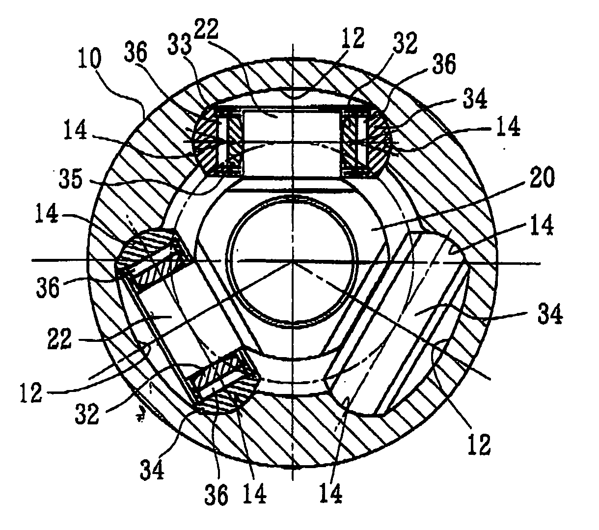
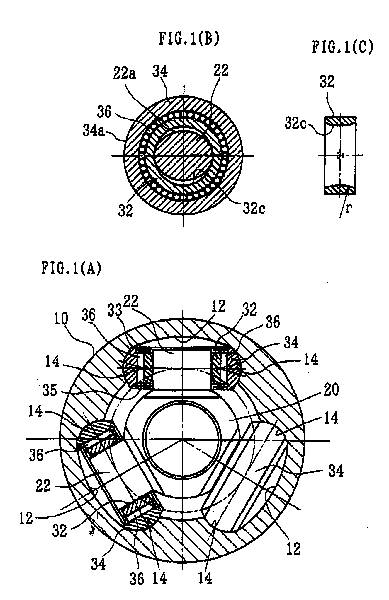
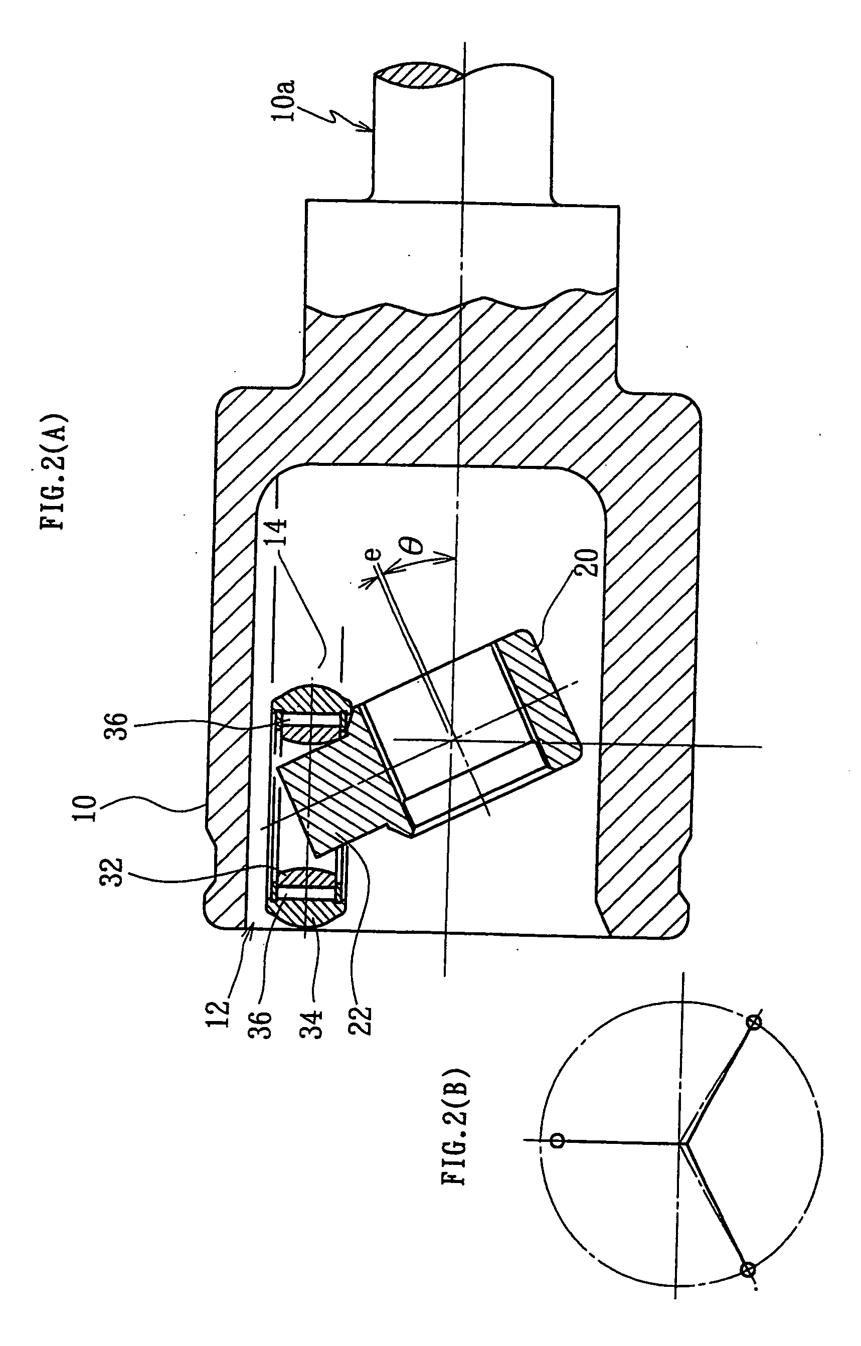
[0084] FIGS. 1(A) through 2(B) show the present invention. FIG. 1(A) shows a cross section of the joint, FIG. 1(B) a section perpendicular to a trunnion, and FIG. 1(C) a section of a support ring. FIG. 2(A) shows a longitudinal section of the joint at an operating angle (.).
[0085] As shown in FIGS. 1(A)-1(C), the constant velocity universal joint is chiefly composed of an outer joint member 10 and a tripod member 20. One of two shafts to be coupled is connected to the outer joint member 10, and the other is to the tripod member 20.
[0086] The outer joint member 10 has three track grooves 12 axially extending in its inner periphery. Each of the track grooves 12 has roller guideways 14 formed on its circumferentially-opposed side walls. The tripod member 20 has three trunnions 22 which are projected radially. Each of the trunnions 22 carries a roller 34, and this roller 34 is accommodated in one of the track grooves 12 in the outer joint member 10. The outer peripheries 34a of the rol...
second embodiment
[0103] FIGS. 3(A) through 4 show the present invention. This second embodiment differs from the above-described first embodiment only in that the generator to the inner peripheries 32c of the support rings 32, which has been a single arc in the first embodiment, consists of a combination of an arc portion 32a at the center and relief portions 32b on both sides. The role of the relief portions 32b is to avoid the interference with the trunnions 22 at an operating angle (.) as shown in FIG. 3(C). Each relief portion 32b is formed by a straight or curved line that gradually spreads out from an edge of the arc portion 32a to an end of the support ring 32. The relief portions 32b illustrated here are formed by part of a conical surface having a vertex angle=50°. The arc portions 32a have a large radius of curvature (r) on the order of e.g. 30 mm, so as to allow the trunnions 20 to tilt 2-3° or so with respect to the support rings 32. In tripod type constant velocity universal joints, one...
PUM
 Abstract
Description
Claims
Application Information
 - R&D Engineer
- R&D Manager
- IP Professional
- Industry Leading Data Capabilities
- Powerful AI technology
- Patent DNA Extraction
Browse by: Latest US Patents, China's latest patents, Technical Efficacy Thesaurus, Application Domain, Technology Topic.
© 2024 PatSnap. All rights reserved.Legal|Privacy policy|Modern Slavery Act Transparency Statement|Sitemap