Belt-type continuous stepless speed changer
- Summary
- Abstract
- Description
- Claims
- Application Information
AI Technical Summary
Benefits of technology
Problems solved by technology
Method used
Image

Examples
first embodiment
[0049] the invention will be hereinafter explained with reference to FIGS. 1 to 12.
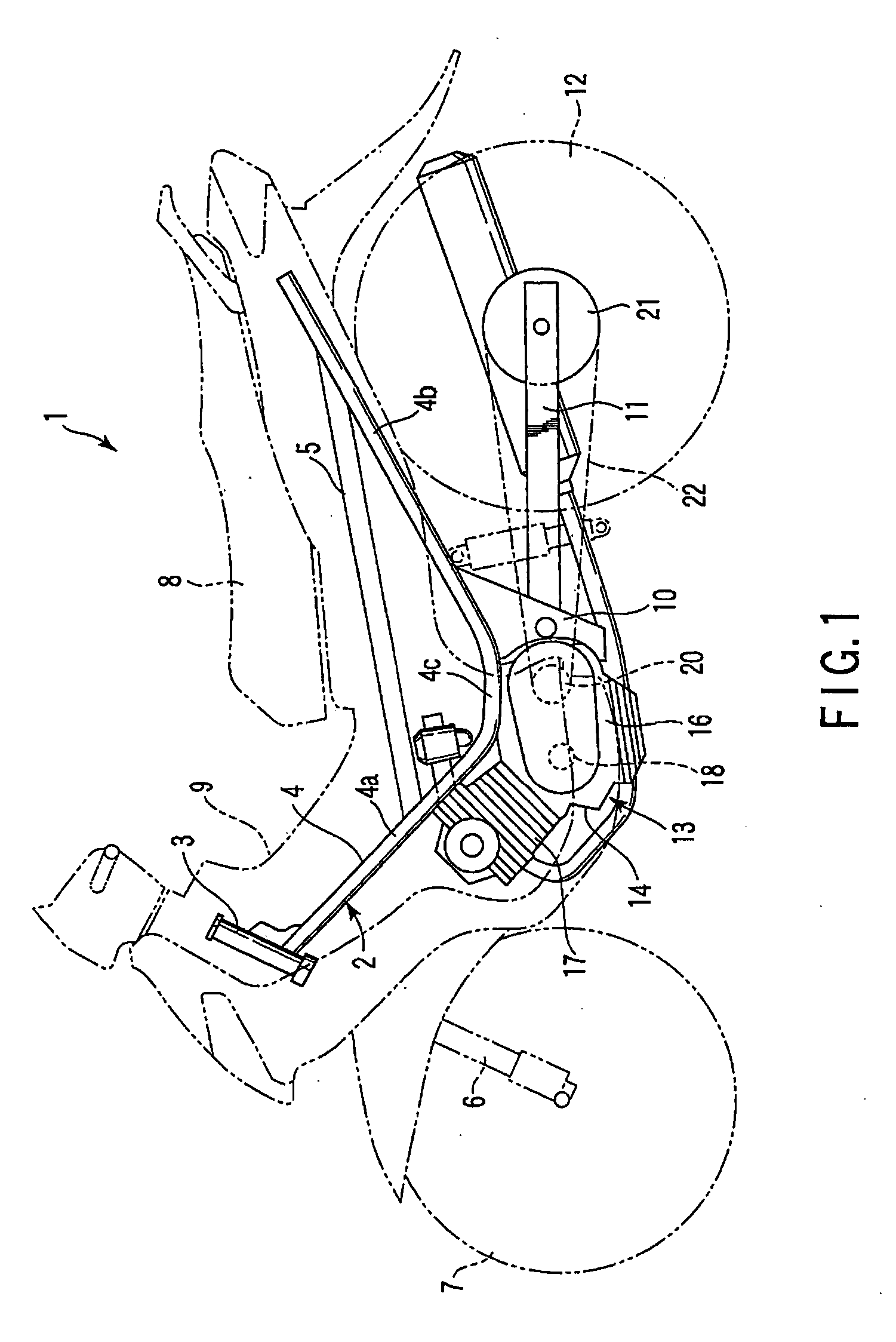
[0050]FIG. 1 discloses a motorcycle 1 that is an example of a vehicle according to the invention. The motorcycle 1 has a frame 2. The frame 2 includes a steering head pipe 3, a pair of main pipes 4 (only one main pipe 4 is shown) and a pair of seat rails 5 (only one seat rail 5 is shown). The steering head pipe 3 is located at a front end of the frame 2 and supports a front wheel 7 via a front fork 6.
[0051] Each of the main pipes 4 extends rearwards from the steering head pipe 3. The main pipe 4 includes a front-half portion 4a that extends obliquely downward from the steering head pipe 3, a rear-half portion 4b that extends obliquely upward from a lower end of the front-half portion 4a, and an intermediate portion 4c that is located between the front-half portion 4a and the rear-half portion 4b.
[0052] The seat rail 5 is suspended between the front-half portion 4a and the rear-half portion 4b of the...
third embodiment
[0107]FIGS. 15 and 16 disclose the invention.
[0108] In the third embodiment, the fixed plate 34a of the primary sheave 29 is described as an example. As shown in FIG. 15, plural rib-like projections 81 are formed on the first clamp surface 37a of the fixed plate 34a. The projections 81 extend radially from the rotational center of the fixed plate 34a over the entire first clamp surface 37a. The projections 81 define plural radial grooves 82 over the first clamp surface 37a. The projections 81 and the grooves 82 are alternately arranged on the first clamp surface 37a. Consequently, the entire first clamp surface 37a functions as a high friction portion 83 with a high friction coefficient.
[0109] Although not shown, the first clamp surface 37a is coated with the same friction layer as in the first embodiment. The friction layer is stacked on the first clamp surface 37a to thickness sufficient for filling the projections 81 and the grooves 82.
[0110] According to this structure, since ...
fourth embodiment
[0111]FIG. 17 discloses the invention.
[0112] In the fourth embodiment, the contact surfaces 58a and 58b of the belt 31 are covered with friction layers 63 which increases the friction. The structure of the belt 31 is the same as that in the first embodiment. In addition, as in the first embodiment, the friction layers 63 contain infusible carbon powder.
[0113] According to the fourth embodiment, the friction layers 63 are stacked on the contact surfaces 58a and 58b of the belt 31 to thickness sufficient for filling the uneven portions of the contact surfaces 58a and 58b of the belt 31.
[0114] When the new belt 31 is wound between the primary sheave and the secondary sheave, the friction layers 63 are interposed between the belt 31 and both the sheaves. In the initial stage of driving, the carbon powder contained in the friction layers 63 enters slight gaps between the belt 31 and both the sheaves. Consequently, contact areas between the belt 31 and the respective sheaves increase. A...
PUM
 Abstract
Description
Claims
Application Information
 - Generate Ideas
- Intellectual Property
- Life Sciences
- Materials
- Tech Scout
- Unparalleled Data Quality
- Higher Quality Content
- 60% Fewer Hallucinations
Browse by: Latest US Patents, China's latest patents, Technical Efficacy Thesaurus, Application Domain, Technology Topic, Popular Technical Reports.
© 2025 PatSnap. All rights reserved.Legal|Privacy policy|Modern Slavery Act Transparency Statement|Sitemap|About US| Contact US: help@patsnap.com