System for three-phase voltage detection and protection

a three-phase voltage and protection technology, applied in the field of three-phase (3-phase) voltage detection, can solve the problems of time delay in response to voltage fault, inability to implement above-rms calculation methods, and long computations, and achieve simple and accurate calculation methods, fast dynamic performance, and substantially improved dynamic response to grid voltage faults

Inactive Publication Date: 2007-01-04
CHANG LIUCHEN +1
View PDF4 Cites 33 Cited by
  • Summary
  • Abstract
  • Description
  • Claims
  • Application Information

AI Technical Summary

Benefits of technology

[0006] In one aspect, the present invention provides a method and system in which the continuous accumulation over time is no longer necessary, and the dynamic response to a grid voltage fault is substantially improved by a method for three-phase grid voltage detection and protection based on voltage reference frame transformation on a three-phase grid-connected inverter, based on calculation and monitoring of the instantaneous magnitude of the grid voltage vector in the synchronous d-q reference frame. Analysis shows that the magnitude of the grid voltage vector can reflect the dynamic characteristics of grid voltages instantaneously, thus the response for grid voltage faults is immediate. In addition, the method is direct and simple. The results of both simulations and laboratory tests on the inverter have verified that the new method is simple and accurate, and offers a fast dynamic performance.

Problems solved by technology

However, this requires continuously accumulating the sampled voltage data over one or more cycles before an RMS value is calculated, which not only demands lengthy computations but also causes a time delay in response to a voltage fault.
In practice, the above RMS calculation method has certain challenges in implementation.
The discrete values of v(t) or v2(t) at the sampling moments need to be accumulated continuously over one or more cycles, which requires both large computational time and storage resources.
This causes an inevitable delay in response to an over-voltage or under-voltage fault.

Method used


Image

  • System for three-phase voltage detection and protection
  • System for three-phase voltage detection and protection
  • System for three-phase voltage detection and protection

Examples


Embodiment Construction

[0031] For the purposes of promoting an understanding of the principles of the invention, reference will now be made to the embodiment illustrated in the drawings and specific language will be used to describe the same. It will nevertheless be understood that no limitation of the scope of the invention is thereby intended, such alterations and further modifications in the illustrated device, and such further applications of the principles of the invention is illustrated therein being contemplated as would normally occur to one skilled in the art to which the invention relates.

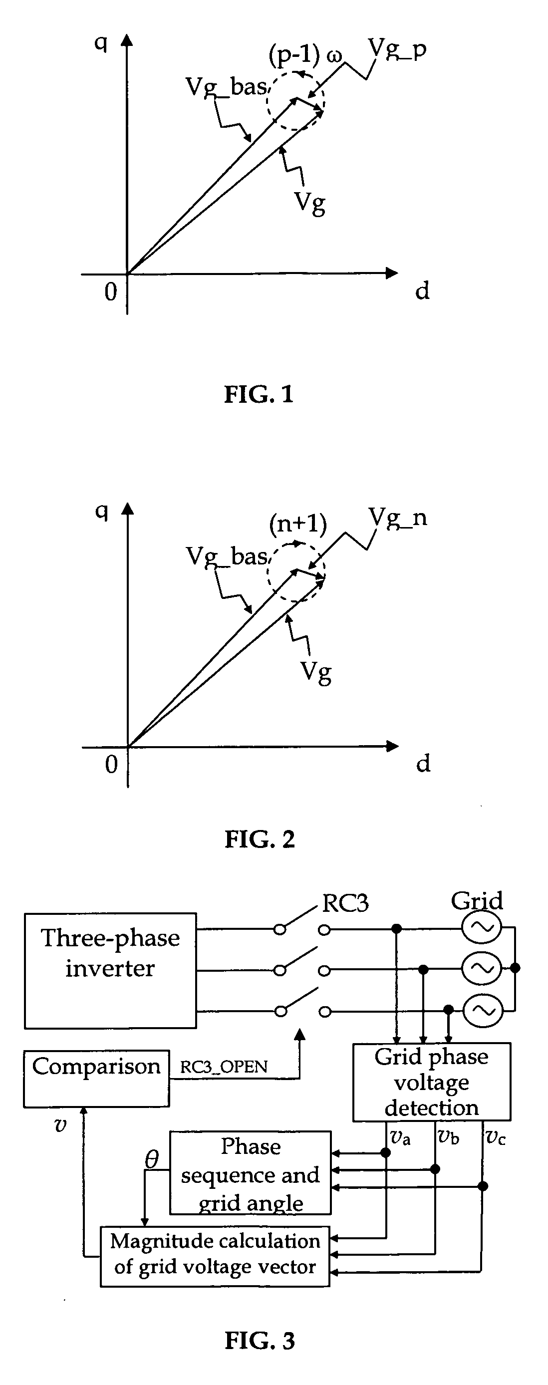
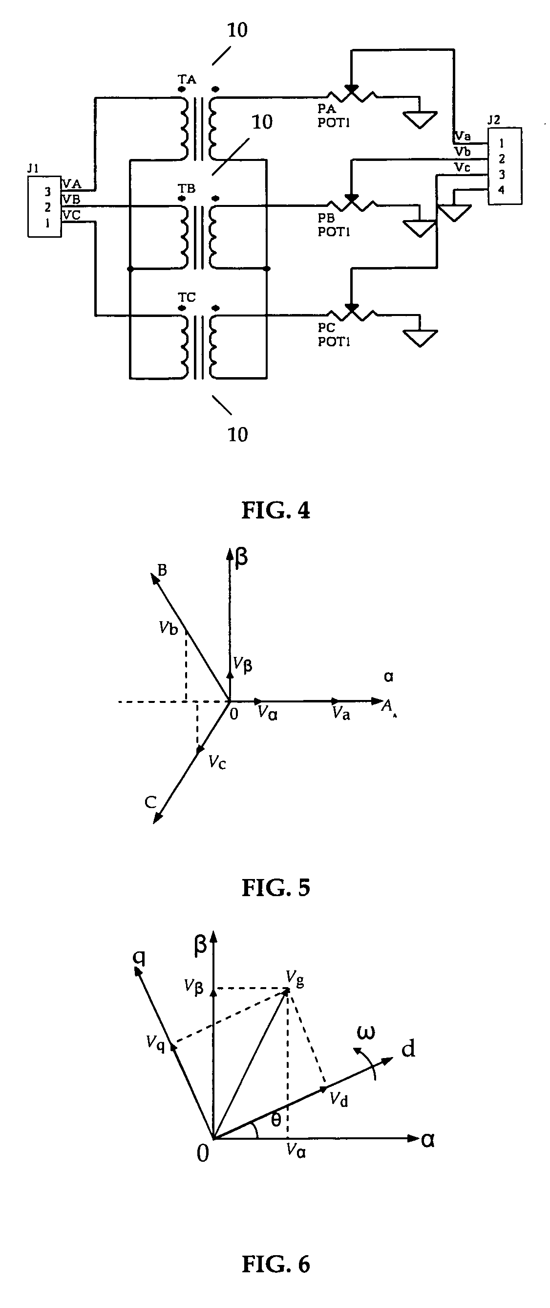
[0032] According to the principles of Park Transformation, three-phase balanced sinusoidal signals in the stationary A-B-C reference frame can be transformed into a static vector in the synchronous d-q reference frame, and the magnitude of this vector is exactly equal to the peak value of the sinusoidal signal. Since the actual grid voltage is generally non-sinusoidal due to harmonic components, the correspond...


PUM


Abstract

A method of system for three-phase voltage detection wherein the magnitude of a grid voltage is calculated using a grid voltage vector derived from the grid voltage using Park Transformation and then compared to a predetermined voltage threshold is disclosed.

Description

CROSS REFERENCE [0001] This application claims priority from and benefit to U.S. provisional patent application Ser. No.: 60 / 691,784 filed on Jun. 20, 2005, which is hereby incorporated by reference in its entirety.FIELD OF THE INVENTION [0002] The present invention relates generally to the field of grid-connected inverter systems and more particularly, to a method and system for three-phase (3-phase) voltage detection. BACKGROUND OF THE INVENTION [0003] Reliable, fast and accurate voltage detection is critical for the safety and protection of distributed power generators (DC) as well as power systems. [0004] A distributed power generation system is required to cease energizing the grid within a specified clearing time at the detection of an abnormal grid voltage. Traditionally, three-phase grid voltage protection is achieved by calculating and monitoring RMS values of grid voltages from the instantaneous voltage data. However, this requires continuously accumulating the sampled vol...

Claims


Application Information

Patent Timeline
Patent Type & Authority Applications(United States)
IPC IPC(8): G05D11/00
CPCG01R19/2513
Inventor CHANG, LIUCHENZENG, QINGRONG
Owner CHANG LIUCHEN
Why Eureka
Try Eureka