Realization method of self-equalized multiple passband filter

a filter and self-equalization technology, applied in waveguide type devices, computation using non-denominational number representations, instruments, etc., can solve the problem that the filter with the in-line structure cannot the filter with the in-line structure may not be able to realize all the transmission zeros, and the bit error rate of both filters in digital data transmission is larg

Inactive Publication Date: 2007-01-04
ELECTRONICS & TELECOMM RES INST
View PDF2 Cites 11 Cited by
  • Summary
  • Abstract
  • Description
  • Claims
  • Application Information

AI Technical Summary

Problems solved by technology

Therefore, it is physically impossible to realize a filter having the in-line structure to provide six transmission zeros.
Therefore, the filter with the in-line structure may not be able to realize all the transmission zeros generated in the filter's transfer functi...

Method used


Image

  • Realization method of self-equalized multiple passband filter
  • Realization method of self-equalized multiple passband filter
  • Realization method of self-equalized multiple passband filter

Examples


Embodiment Construction

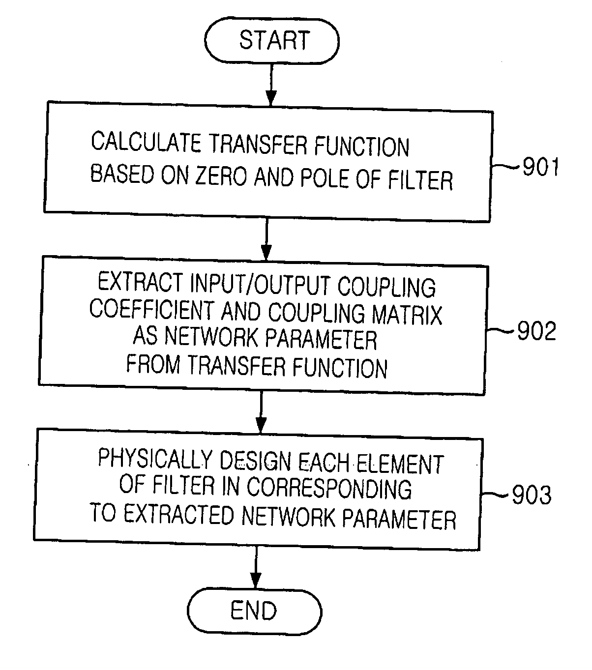
[0032] Reference will now be made in detail to the preferred embodiments of the present invention, examples of which are illustrated in the accompanying drawings.

[0033] A transfer function t(s) represents a frequency characteristic of a filter where the present invention is applied. The transfer function t(s) is expressed as a following equation: t2⁡(s)=11+ɛ2⁢R2⁡(s)(Eq. ⁢1)

[0034] In the Eq. 1, s is a normalized complex frequency, R(s) is a characteristic function representing a characteristic of the filter, and ε is a ripple constant representing a passband ripple characteristic of the filter.

[0035] A response characteristic of a filter is categorized into a butterworth response, a chebyshev response, or an elliptic response according to the characteristic function.

[0036] And, implementation of transmission zeros is required in the multiple passband filter and the elliptic response type is a common response type of a filter having transmission zeros. The characteristics function...


PUM


Abstract

A realization method of a multiple passband filter that equalizes a group delay without using an external equalizer is disclosed. The realization method includes the steps of: a) calculating a transfer function based on poles and zeros; b) extracting an input/output coupling coefficient and a coupling matrix from the calculated transfer function as a network parameter; and c) physically designing and realizing elements of the filter to have the extracted network parameter.

Description

FIELD OF THE INVENTION [0001] The present invention relates to a realization method of a self-equalized multiple passband filter; and, more particularly, to a realization method of a self-equalized multiple passband filter having self-equalized group delay characteristics without using an external equalizer. DESCRIPTION OF THE PRIOR ART [0002] Generally, a microwave filter has characteristics of single passband and plural of cut-off bands at each side of the passband. The microwave filter having the single passband characteristic is classified to a butterworth response filter, a chebyshev response filter and an elliptic response filter based on its response characteristic. The above mentioned microwave filters disclosed at various books and articles including a book by D. M. Pozar, entitled “Microwave Engineering”, Addision-Wesley, 1993. Ch. 9 and another book by J. A. G. Malherbe, entitled “Microwave Transmission Line Filters”, Artech House. 1979. [0003] However, a filter having mu...

Claims


Application Information

Patent Timeline
IPC IPC(8): G06F17/10
CPCH01P1/2082H03H17/00
Inventor LEE, JU-SEOPUHM, MAN-SEOKYOM, IN-BOKPARK, JONG-HEUNG
Owner ELECTRONICS & TELECOMM RES INST
Why Eureka
Try Eureka