Model reduction system and method for component lifing

a component and model reduction technology, applied in the field of diagnostic systems, can solve the problems of inability to take into account the actual operating conditions of the component, the most common failure mode of the engine rotating component is material fatigue, and the general cause of material fatigue, so as to facilitate the use of measured operating conditions, facilitate the improvement of component lifing, and reduce the effect of the component model

Inactive Publication Date: 2007-01-04
HONEYWELL INT INC
View PDF3 Cites 20 Cited by
  • Summary
  • Abstract
  • Description
  • Claims
  • Application Information

AI Technical Summary

Benefits of technology

[0006] The present invention provides a model reduction system and method that facilitates improved component lifing. The model reduction system and method uses a range of operating conditions and system identification techniques to reduce a physics-based component model. Specifically, system identification techniques are used to create a reduced component model. The reduced component model facilitates the use of measured operating conditions in calculating component lifing. Specifically, the reduced component lifing model provides the ability to predict selected parameters of interest at specified critical locations without requiring excessive computations. Thus, the reduced component model can be used with actual measured operating conditions to calculate component lifing over the life of the component. Thus, the reduced component lifing model facilitates improved component lifing calculation.

Problems solved by technology

For example, in rotating components, such as turbine disks in turbine engines, the most common failure mode for engine rotating components is material fatigue.
Material fatigue is generally caused by the stresses and temperatures resulting from start-stop cycles in the turbine engine.
One limitation in calculating component lifing using a standard flight is the inability to take into account the actual operating conditions the component experiences.
Thus, in cases where the actual operating conditions of flights are significantly different than the standard flight used to calculate component lifing, the calculation of the component lifing can be unacceptably inaccurate.
Inaccuracy in the component lifing calculation can cause the component to be repaired or replaced well before the lifetime of the component is actually used up.
In either case, the inaccuracy in component lifing is highly undesirable.

Method used


Image

  • Model reduction system and method for component lifing
  • Model reduction system and method for component lifing
  • Model reduction system and method for component lifing

Examples


Embodiment Construction

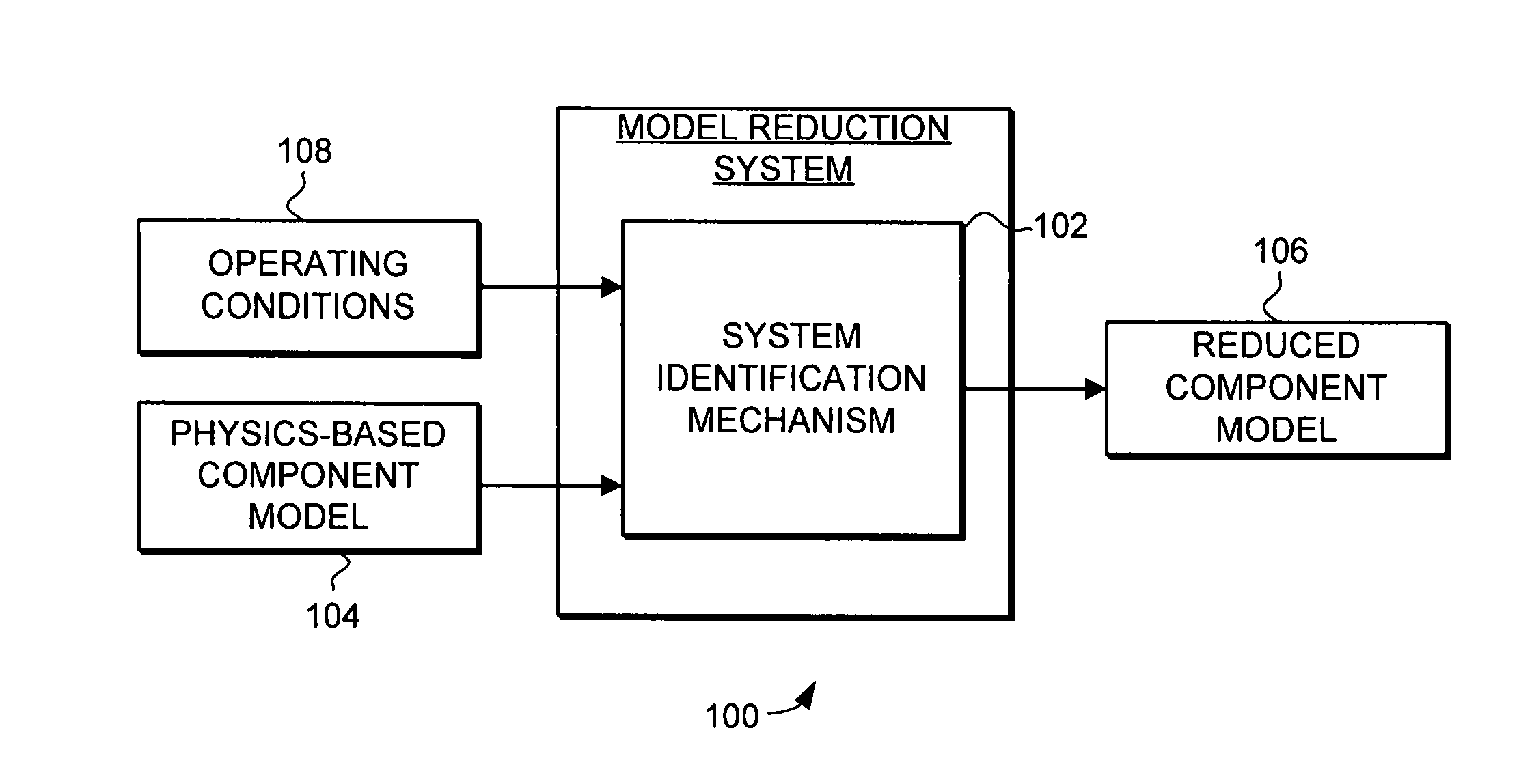
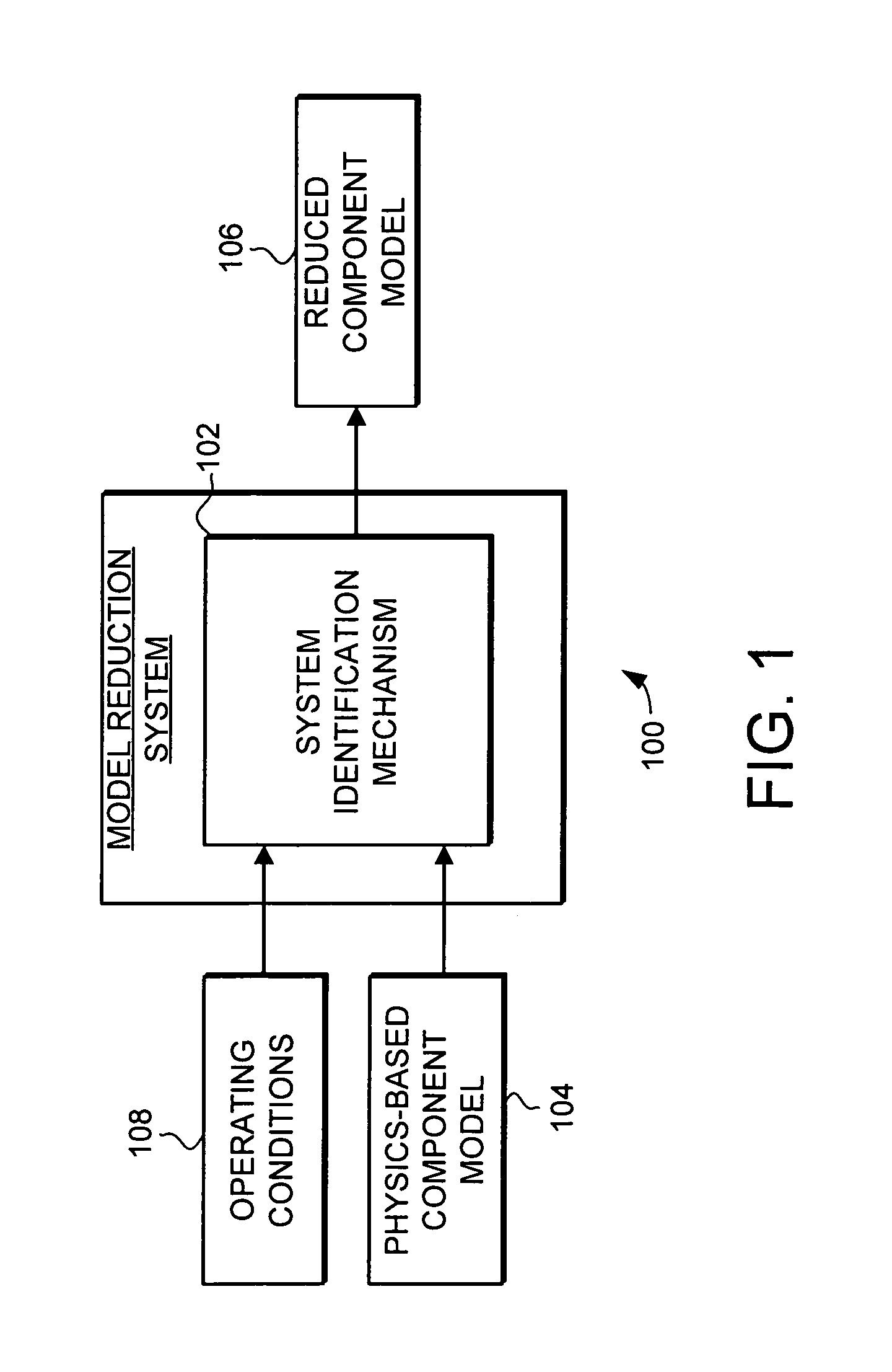
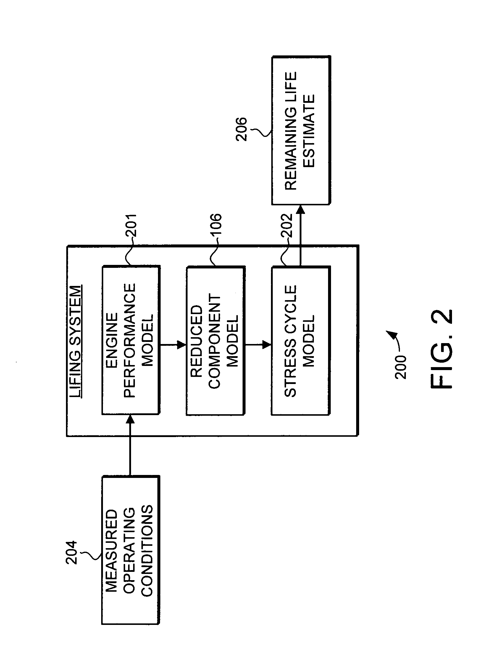
[0018] The present invention provides a model reduction system and method that facilitates improved component lifing. The model reduction system and method uses a range of operating conditions and system identification techniques to reduce a physics-based component model. Specifically, system identification techniques are used to create a reduced component model. The reduced component model facilitates the use of measured operating conditions in calculating component lifing. Specifically, the reduced component lifing model provides the ability to predict selected parameters of interest at specified critical locations without requiring excessive computations. Thus, the reduced component model can be used with actual measured operating conditions to calculate component lifing over the life of the component. Thus, the reduced component lifing model facilitates improved component lifing calculation.

[0019] Turning now to FIG. 1, an exemplary model reduction system 100 is illustrated sch...


PUM


Abstract

A model reduction system and method that facilitates improved component lifing is provided. The model reduction system and method uses a range of operating conditions and system identification techniques to reduce a physics-based component model. Specifically, system identification techniques are used to create a reduced component model. The reduced component model facilitates the use of measured operating conditions in calculating component lifing. Specifically, the reduced component lifing model provides the ability to predict selected parameters of interest at specified critical locations without requiring excessive computations. Thus, the reduced component model can be used with actual measured operating conditions to calculate component lifing over the life of the component. Thus, the reduced component lifing model facilitates improved component lifing calculation.

Description

[0001] This application claims the benefit of U.S. Provisional Application No. 60 / 688,088, filed Jun. 6, 2005.FIELD OF THE INVENTION [0002] This invention generally relates to diagnostic systems, and more specifically relates to component lifing. BACKGROUND OF THE INVENTION [0003] Engines are a particularly critical part of modern aircraft, and the reliability of engines in the aircraft is thus of critical importance. One technique for improving the reliability of engines and other complex systems is to estimate the operational lifetime of critical components in the system and repair or replace those components before those components have an unacceptable probability of failure. [0004] The process of estimating the operational lifetime of a component is generally referred to as component lifing. The techniques used for component lifing generally must be specifically tailored to the component, the operational conditions of the component, and the most common failure modes for the comp...

Claims


Application Information

Patent Timeline
Patent Type & Authority Applications(United States)
IPC IPC(8): G06N3/02
CPCG06F17/5018G06F2217/80G06F17/5095G06F30/15G06F30/23G06F2119/08
Inventor PARTHASARATHY, GIRIJA
Owner HONEYWELL INT INC
Why Eureka
Try Eureka