Optical sensor with co-located pressure and temperature sensors

Active Publication Date: 2007-01-11
BAKER HUGHES INC
View PDF24 Cites 78 Cited by
  • Summary
  • Abstract
  • Description
  • Claims
  • Application Information

AI Technical Summary

Benefits of technology

[0011] The present invention is directed to an optical sensor adapted for use in the oil and gas wells that has at least two sensing regions. Each sensing region preferably measures one environmental condition, e.g., pressure, temperature, tilt angle of the well bore, position, vibration, acoustic waves, chemicals, chemical con

Problems solved by technology

Such application has not extended into the petroleum industry due to the severe environment encountered downhole.
However, the temperature within an oil well increases wi

Method used


Image

  • Optical sensor with co-located pressure and temperature sensors
  • Optical sensor with co-located pressure and temperature sensors
  • Optical sensor with co-located pressure and temperature sensors

Examples


Embodiment Construction

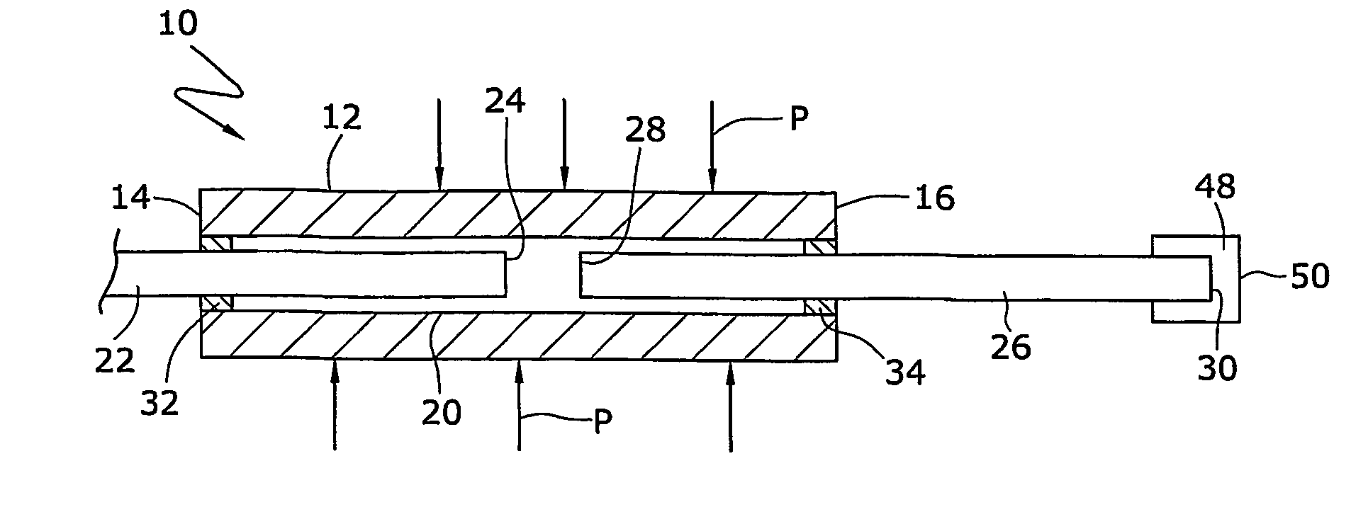
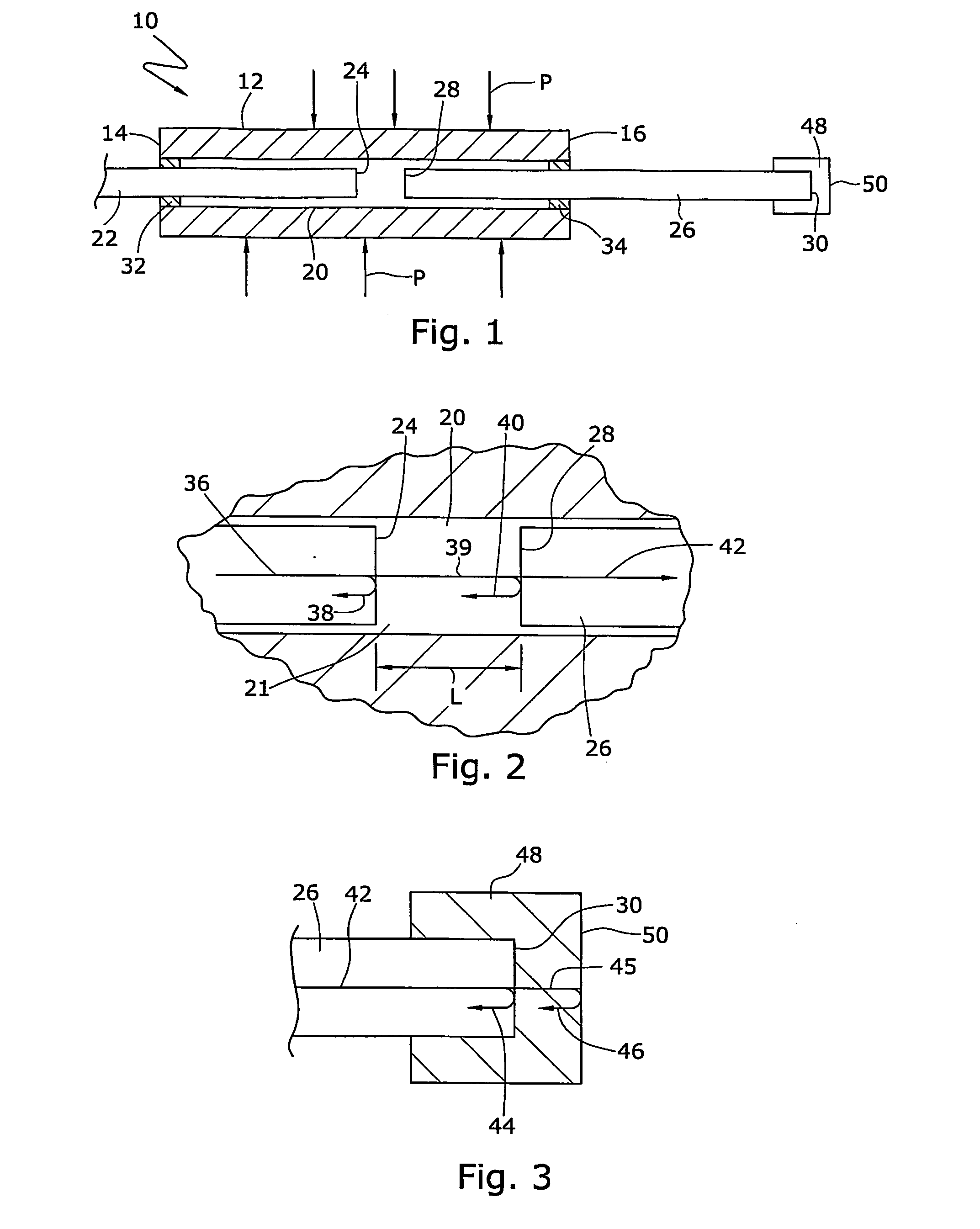
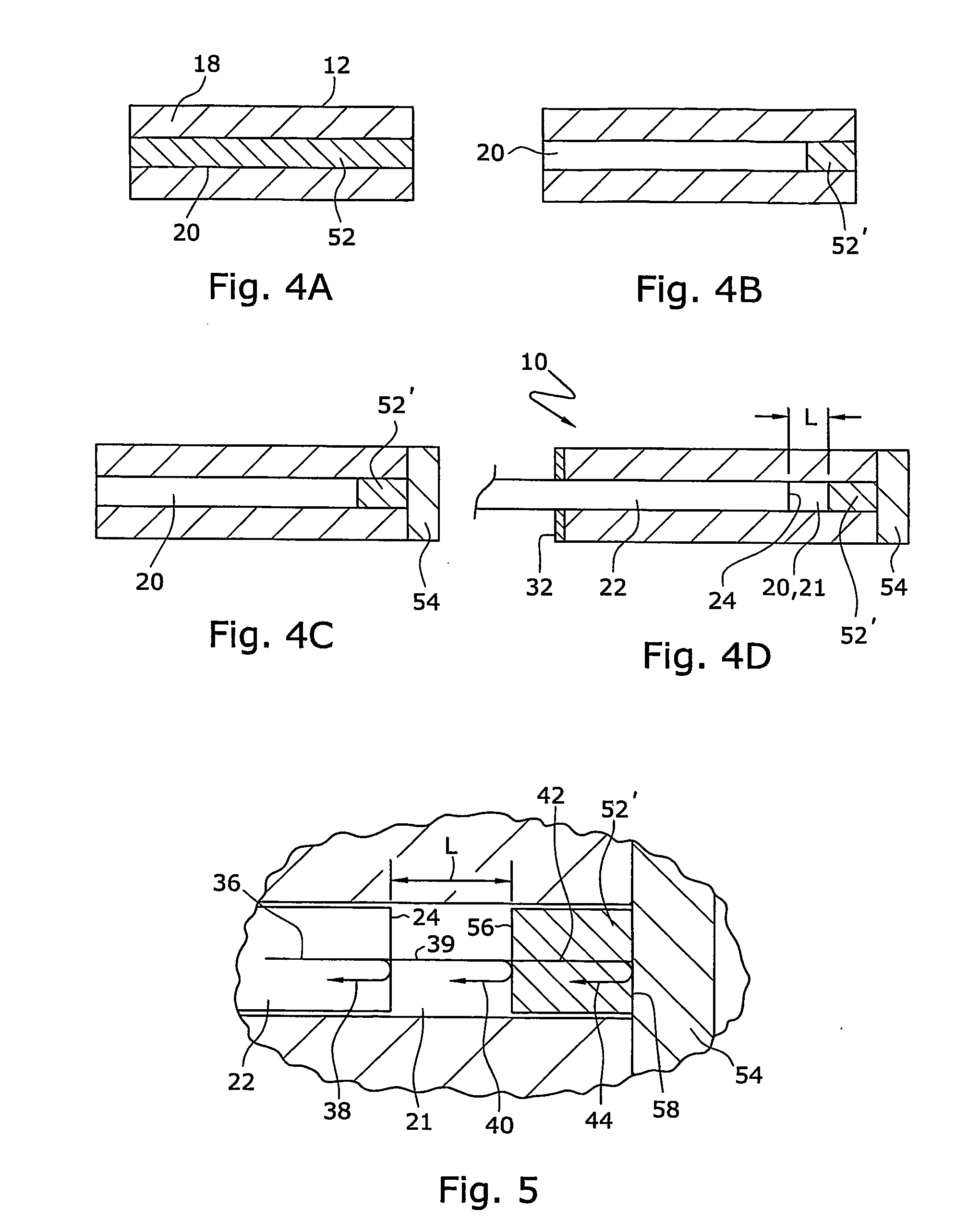
[0046] Referring initially to FIG. 1, an embodiment of optical sensor 10 in accordance with the present invention includes tube 12, which has first end 14 and second end 16 and relatively thick wall 18 extending between the two ends. Tube 10 defines cavity 20 therewithin. At least one input / output or launch waveguide or fiber 22 is inserted into cavity 20 at first end 14 and reflective waveguide or fiber 26 is inserted into cavity 20 at second end 16. The term “waveguide” and “fiber” are used interchangeably herein and include, but are not limited to, any optical fiber, optical waveguide, fiber core, fiber core plus cladding and any optical structure capable of transmitting light. First end 24 of launch fiber 22 is spaced apart from first end 28 of reflective fiber 26 by spatial gap 21 having a length “L”. Second end 30 of reflective fiber 26 is attached to cap 48. Cap 48 contains a temperature sensitive material therewithin and has distal end 50. Although cavity 20 and gap 21 illus...


PUM


Abstract

An optical sensor (10) that provides for concurrent pressure and temperature measurements at substantially the same location includes at least one launch fiber (22) and at least one temperature sensitive material (52) having a refractive index that changes with a change in temperature. The launch fiber and temperature sensitive material are spaced from each other across a gap (21) having length (L). A reflecting fiber (26) can be provided adjacent the temperature sensitive material. The optical sensor (10) also includes a sealed cavity (20). The launch fiber (22) and reflecting fiber (26) can be attached to the tube and at least partially disposed within the cavity. Changes in pressure change the length (L) of the gap (21).

Description

CROSS-REFERENCE TO RELATED APPLICATIONS [0001] The present application is a continuation-in-part application of co-pending U.S. patent application Ser. No. 10 / 653,996, filed on Sep. 4, 2003 and of co-pending U.S. provisional patent application No. 60 / 499,725, filed on Sep. 4, 2003. The entire disclosures of these applications are incorporated herein by reference.FIELD OF THE INVENTION [0002] This present invention relates to optical sensors, and more particularly to fiber optic systems having at least two sensors located proximate to each other. BACKGROUND OF THE INVENTION [0003] Optical fibers have become a communication medium of choice for carrying information, in particular for long distance communication because of the excellent light transmission characteristics over long distances and the ability to fabricate optical fibers in lengths of many kilometers. The information being communicated includes video, audio or data. The ability to transmit data signals is utilized in appli...

Claims


Application Information

Patent Timeline
IPC IPC(8): G01L1/24G01D5/353G01K11/32G01L9/00G01L11/02G01L19/00
CPCG01K11/3206G01L9/0077G01L11/025G01L19/0092G01D5/268G01D5/35312
Inventor ZERWEKH, PAULBOYD, CLARKCHILDERS, BROOKSBLEVINS, DANIEL
Owner BAKER HUGHES INC
Why Eureka
Try Eureka