
Electric grill

a grill and electric technology, applied in the field of electric grills, can solve the problems of uneven cooking of food, complicated cooking system, cumbersome and cumbersome cooking system,

Inactive Publication Date: 2007-01-11
SOUTH ASIA INT H K
View PDF1 Cites 37 Cited by
  • Summary
  • Abstract
  • Description
  • Claims
  • Application Information

AI Technical Summary

Benefits of technology

[0019] The present invention is a new type of electric grill comprised of a lower cooking assembly and an upper cooking assembly pivotally mounted on the lower cooking assembly for rotation about a substantially horizontal axis by means of a foldable hinge, the lower and upper cooking assemblies comprising between them a cooking chamber. The cooking chamber can be positioned at various angles relative to the horizontal axis such that fat and other juices released from the food during the cooking process can drain in varying degrees into a drip tray located underneath the cooking chamber, allowing for different cooking results from extremely dry food to juicy food and in between. The size and volume of the cooking chamber can be varied to accommodate a wide range of foods by means of the foldable hinge.
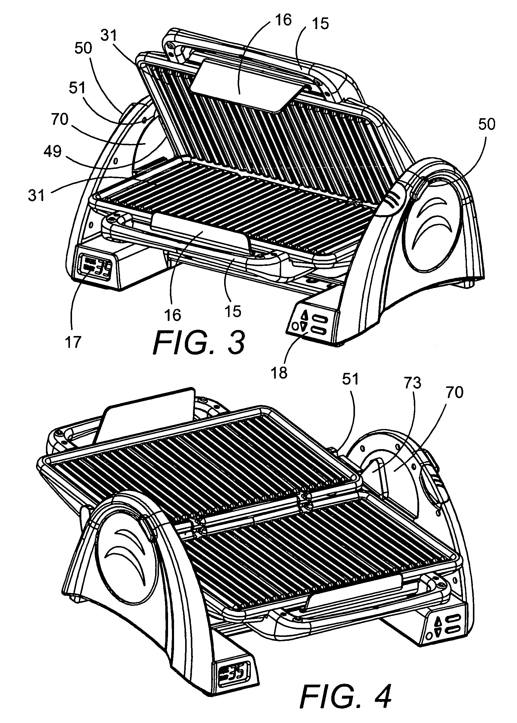
[0020] An electric grill comprising a support structure having top and bottom heating sections is disclosed. The top heating section has a top cooking surface and the bottom heating section has a bottom cooking surface. The top and bottom heating sections are connected to the support structure and at least one section is pivotally associated with the support structure to move between a closed position at which the cooking surfaces are facing one another and an open position at which the surfaces are at an angle to one another that is equal to or greater than 90 degrees. In a closed position, the top heating section is preferably directly on top of and facing the bottom heating section, which lowers the required cooking time by cooking the food on two sides. Moreover, the top heating section may be in an open position such that the top heating section is perpendicular to the bottom heating section. This open position allows the user to easily place food on the bottom cooking surface, and can also be used to cook food only on one side. The top heating section may be opened to 180 degrees such that the top and bottom heating sections can both be used as a flat cooking surface on which food may be placed. The support structure preferably includes a tilting mechanism which supports the top and bottom heating sections in a plurality of angular positions.
[0022] An additional aspect of this invention may include an at least one hinge to which the top and bottom heating sections are connected and which allows the aforementioned pivoting. The hinge is preferably of the type that can float to accommodate various sizes of food. This allows the top heating section to always be in contact with the food by maintaining a parallel position as compared to the bottom heating section, when in the closed position. An electric grill that can maintain the top heating section parallel to the bottom heating section cooks the food more evenly over the entire surface of the food.
[0025] The tilting mechanism, in a preferred embodiment, comprises a gear allowing releasable fixation of the top and bottom heating sections at a number of discrete angular positions. The tilting mechanism is more preferably a gear-toothed wheel in conjunction with a rod which fits within two teeth of the gear-toothed wheel. When the rod engages the wheel the top and bottom heating surfaces are locked in place and when the rod is disengaged the combination of the top and bottom heating surfaces can move freely. The rod preferably engages and disengages the wheel by a user-operated push button. The series of gear teeth are preferably spaced to allow for fine adjustment, i.e. five degree increments. However, it is also anticipated that the tilting mechanism may allow for infinitely adjustable releasable fixation of the top and bottom heating sections. Holding handles located on the front of both the top and bottom heating sections, the button may be pushed by the user which removes the rod from the gear wheel. The heating sections, as a single unit, are then adjusted, by manually moving the top and bottom heating sections using the handles, to the desired angle and the button is released. Upon release of the button, the rod re-engages the gear wheel at the desired angle and locks the heating sections at the desired angle. The angular positioning can preferably adjust the top and bottom heating sections to an angle from 0 to 60 degrees.
[0029] Furthermore, the electric grill may preferably include a drip tray, heat shield, splatter guard and a cross member. The cross member is located on the base of the grill and provides additional stability.

Problems solved by technology

However, an all too common problem occurs when cooking larger food because the top heating surface cannot remain parallel to the bottom heating surface.
As a result, the food is cooked unevenly because it is being pinched on one side by the misaligned top heating surface.
The grills that attempt to resolve this require the use of springs, or other extraneous techniques and mechanisms, to create a cumbersome and complicated cooking system.
Moreover, these past solutions limit movement of the top cooking surface, and thus still create problems when cooking larger food.
Additionally, these techniques and systems further limit the various methods of cooking possible on the electric grill.
The constraint on the possible cooking angles severely limits the use of the electric grill.
Therefore, if the user desires to cook only one side of the food, the top heating surface remains in its perpendicular position and is left unused.
There is no way to regulate the temperature of the top and bottom heating surfaces individually.
However, the more fat and juices removed during the cooking process, the drier the resulting food will be.
The disadvantage of the prior art grills is that these grills do not allow a person to vary the amount of fat and juices removed during the cooking process according to individual preference or to achieve varying results for different meats cooked in the grills.
Another disadvantage of prior art grills is that the cooking chamber is typically fixed in size and volume.
Therefore, the thickness of foods that may be cooked in the grill is limited.

Method used


Image

  • Electric grill
  • Electric grill
  • Electric grill

Examples


Embodiment Construction

[0044] In the following is described the embodiments of the electric grill which is the present invention. In describing the embodiments illustrated in the drawings, specific terminology will be used for the sake of clarity. However, the invention is not intended to be limited to the specific term so selected, and it is to be understood that each specific term includes all technical equivalents that operate in a similar manner to accomplish a similar purpose.

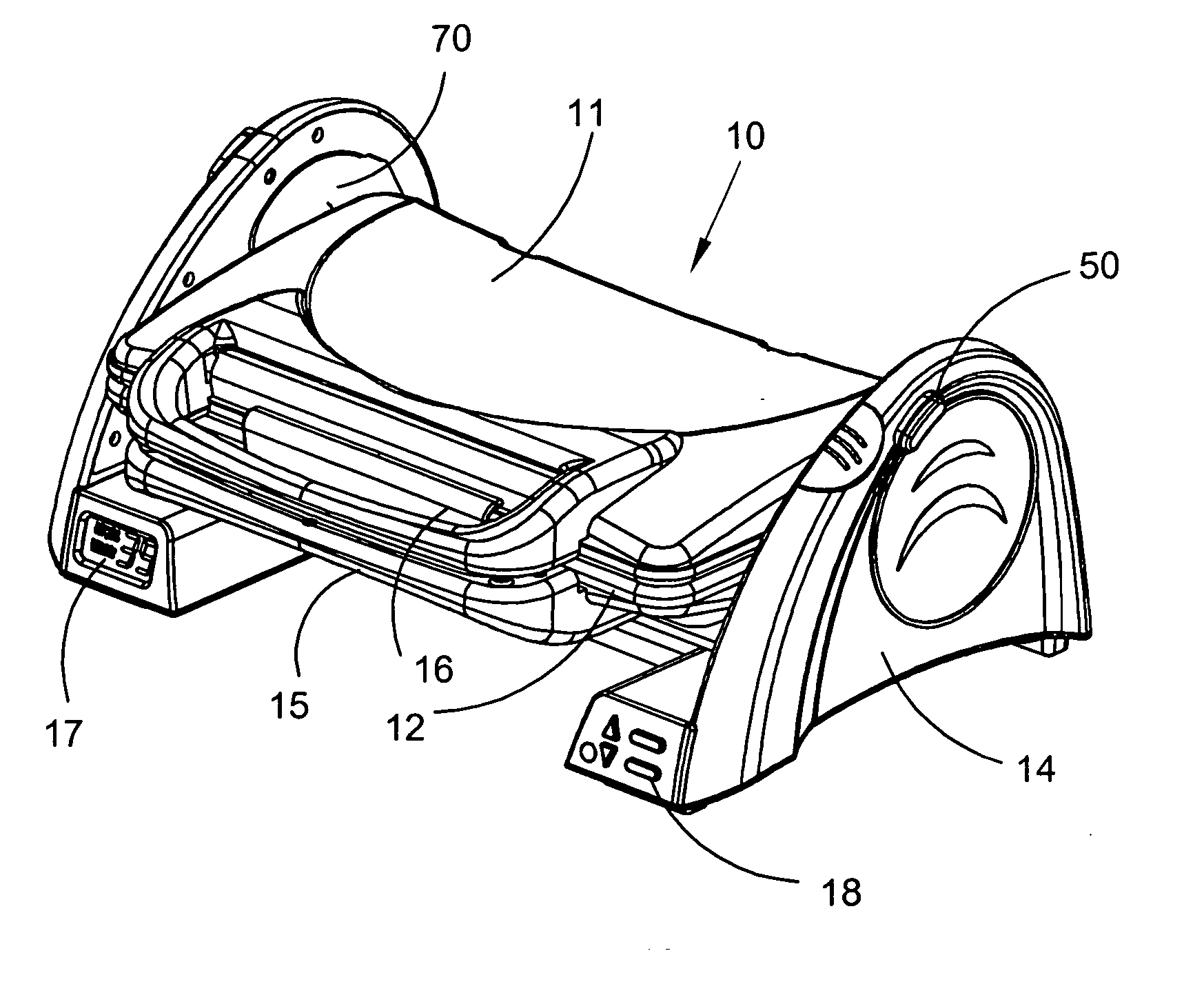
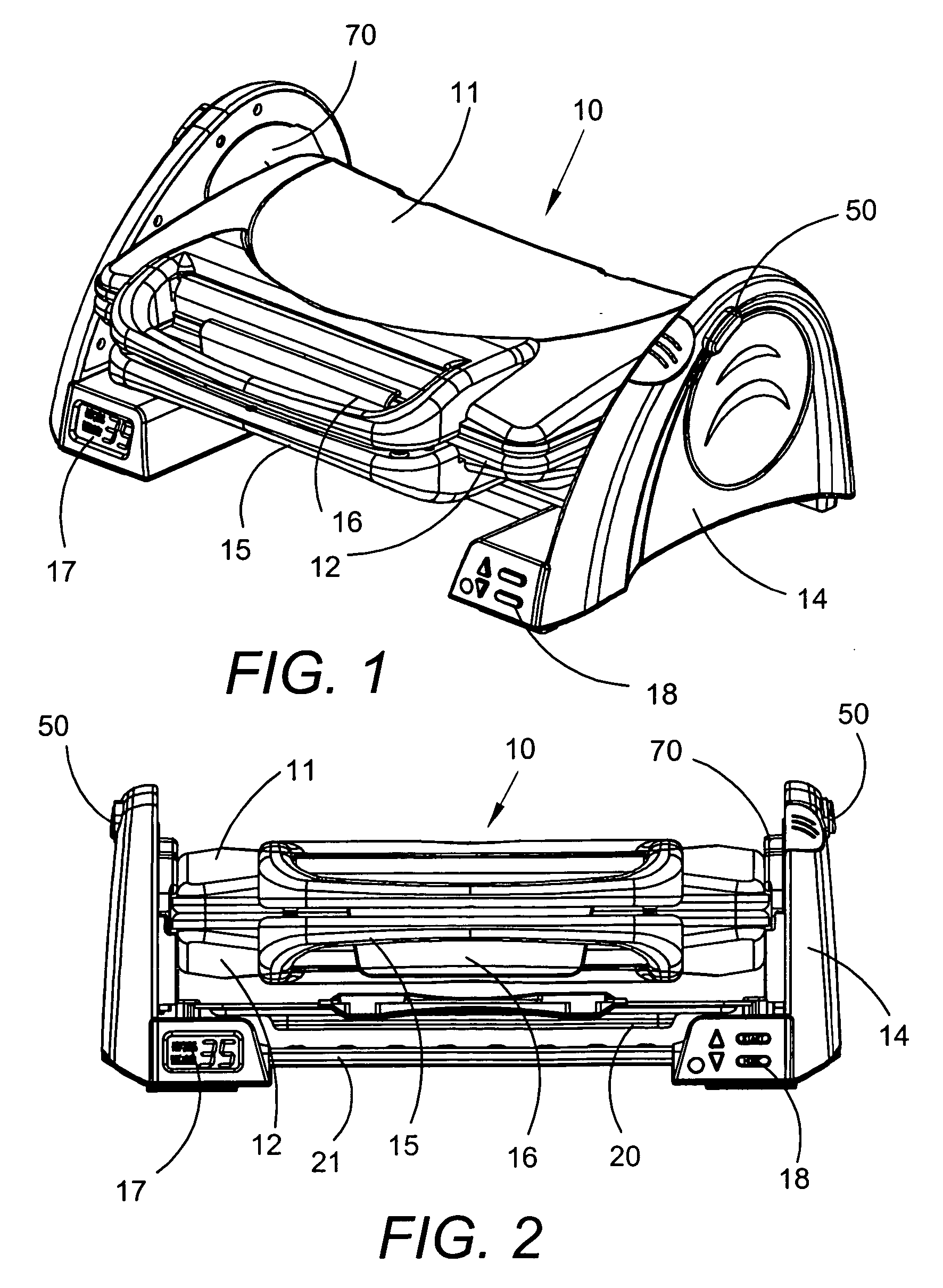
[0045] Referring to the figures, FIG. 1 depicts a perspective view of an electric grill in accordance with the preferred embodiment of the present invention. As shown, the electric grill 10 has a top heating section 11 and a bottom heating section 12 attached to a support structure 14 by two hinges 70. The hinges 70 attach to the rear portion of both the top and bottom heating sections 11 and 12 which allows the top heating section 11 to pivot on its rear side such that the top heating section 11 lifts up from the bottom heatin...


PUM


Abstract

An electric grill for use to create healthier meals is disclosed. The electric grill comprises a support structure which holds a top heating section and a bottom heating section connected by a hinge. The hinge allows for a wide range of movement whereby the top heating section may be face to face with the bottom heating section, may be perpendicular, or may be at a 180 degree angle. Moreover, the top and bottom heating sections may be tilted such that excess grease, oils and juices may be separated from the food being cooked. The electric grill disclosed herein also may include a digital read-out display and a user input keypad.

Description

CROSS REFERENCE [0001] This application is a Continuation-in-Part of the U.S. design patent application Ser. No. 29 / 216,943 filed Nov. 10, 2004 in the name of Raymond (Hoi-Tak) Lam and entitled “Electric Grill.” That application is incorporated herein by reference. This present application claims the benefit of U.S. Provisional Patent Application 60 / 779,944, titled TILTABLE PANINI GRILL, filed on Mar. 7, 2006. The disclosure of said application is incorporated by reference herein.BACKGROUND OF THE INVENTION [0002] The present invention relates to electric grills which are commonly used to create more healthy meals. Grills of this type commonly separate excess oils and juices from the food being prepared, such that the cooked food has a lower fat and cholesterol content. [0003] Many such grills are well known in the art. These grills typically include a bottom heating surface and an upper heating surface which, when an electric current is introduced, become hot enough to cook various...

Claims


Application Information

Patent Timeline
Patent Type & Authority Applications(United States)
IPC IPC(8): A47J37/06
CPCA47J37/0611
Inventor LAM, RAYMOND HOI-TAK
Owner SOUTH ASIA INT H K
Learn More