Loop-type heat exchange device

a heat exchange device and loop-type technology, applied in the direction of semiconductor devices, lighting and heating apparatus, electrical apparatus, etc., can solve the problems of reducing the workability and stability affecting the workability of the heat exchange device, and the cooling device such as the heat sink plus the cooling fan is no longer qualified or desirable for removing the heat from these electronic components, so as to reduce the amount of vapor

Inactive Publication Date: 2007-01-11
HON HAI PRECISION IND CO LTD
View PDF6 Cites 26 Cited by
  • Summary
  • Abstract
  • Description
  • Claims
  • Application Information

AI Technical Summary

Benefits of technology

[0008] The present invention relates to a loop-type heat exchange device for removing heat from a heat-generating component. The heat exchange device includes an evaporator, a condenser, a vapor conduit and a liquid conduit. The evaporator defines therein a chamber for containing a working fluid. The chamber is divided into two regions. The working fluid is capable of turning into vapor in the evaporator upon receiving the heat at one region of said chamber from the heat-generating component. Each of the vapor and liqui...

Problems solved by technology

As a result, the amount of heat generated by these electronic components during their normal operations is commensurately increased, which in turn will adversely affect their workability and stability.
However, currently well-known cooling devices such as heat sink plus cooling fan are no longer qualified or desirable for removing the heat from these electronic components due to their low heat removal capacity.
However, if the rotation speed of the cooling fan is increased, problems such as large noise will inevitably be raised.
On the other hand, by increasing the size of the heat sink, it will make the cooling device ...

Method used


Image

  • Loop-type heat exchange device
  • Loop-type heat exchange device
  • Loop-type heat exchange device

Examples


first embodiment

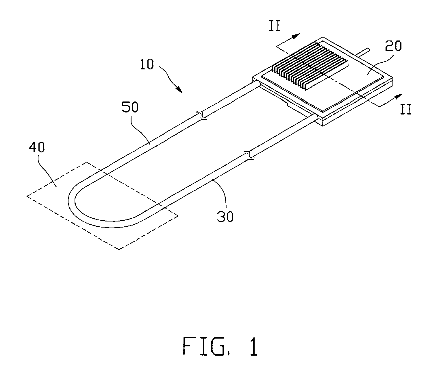
[0017]FIG. 1 illustrates a loop-type heat exchange device 10 in accordance with the present invention. The heat exchange device 10 includes an evaporator 20, a vapor conduit 30, a condenser 40 (shown in broken lines) and a liquid conduit 50. The evaporator 20 preferably is made of two separable portions connected together, as will be discussed in more detail later. The vapor and liquid conduits 30, 50 lie in parallel to each other, although they are not limited to this relationship. Two ends of each of the vapor and liquid conduits 30, 50 are respectively connected to the evaporator 20 and the condenser 40. The vapor and liquid conduits 30, 50 preferably are made of flexible metal or non-metal materials so that they could be bent or flattened easily in order to cause the heat exchange device 10 to be applicable in electronic products having a limited mounting space such as notebook computers.

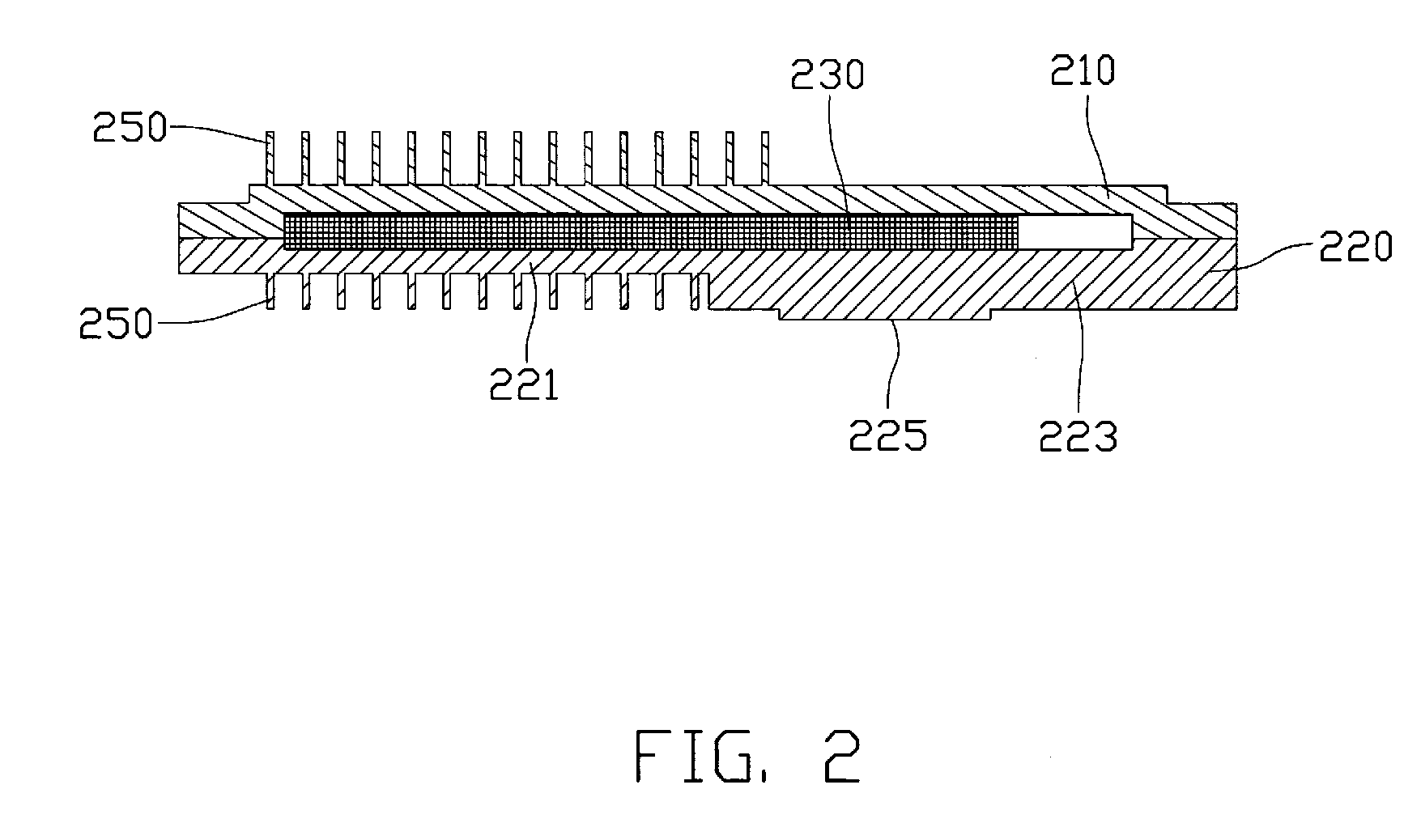
[0018] The evaporator 20 contains therein a working fluid (not shown). As heat from a heat s...

second embodiment

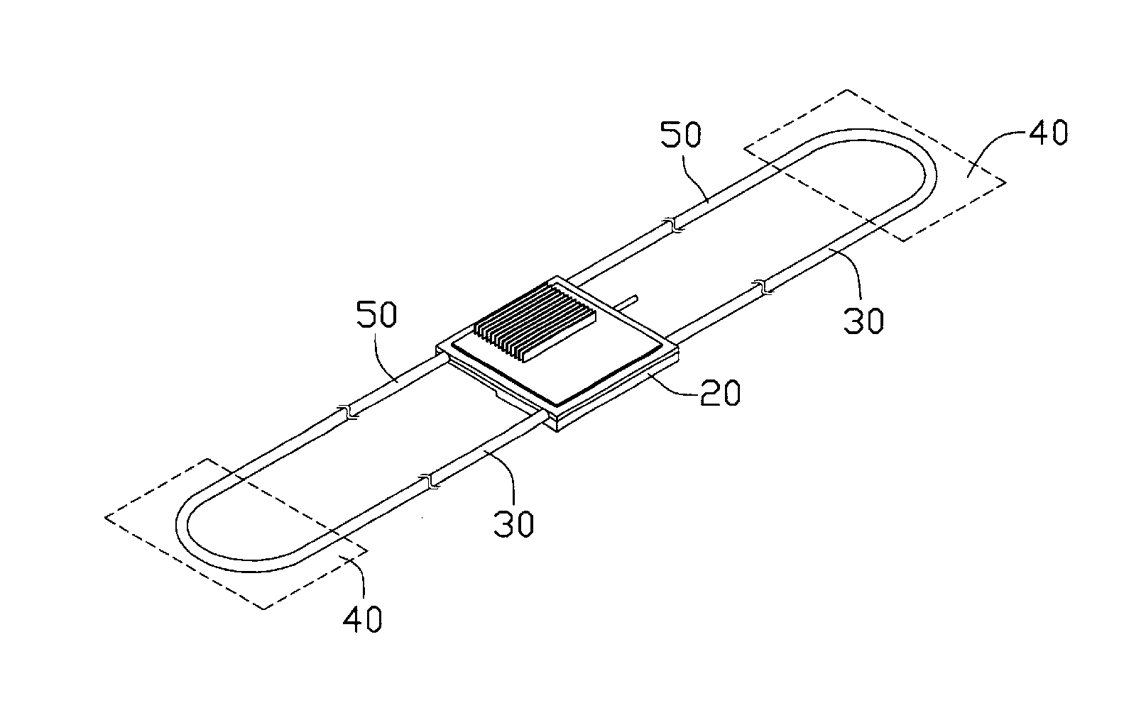
[0027]FIG. 5 shows a loop-type heat exchange device (not labeled) in accordance with the present invention. In this embodiment, the heat exchange device is provided with two heat transfer loops in order to increase its heat removal capacity, thus making it applicable for removing heat from heat-generating components with a high cooling requirement.

third embodiment

[0028]FIG. 6 shows a loop-type heat exchange device (not labeled) in accordance with the present invention. In this embodiment, the heat exchange device includes two heat transfer loops and in each heat transfer loop two vapor conduits 30 are provided so as to reduce a resistance to the vapor generated in the evaporator 20 as it flows towards the condenser 40. To attain this purpose (i.e., reducing resistance to the vapor), the vapor conduit 30 may also be made to have a larger diameter than the liquid conduit 50 so as to enable the generated vapor to move towards the condenser 40 effectively and smoothly.


PUM


Abstract

A loop-type heat exchange device (10) is disclosed, which includes an evaporator (20), a condenser (40), a vapor conduit (30) and a liquid conduit (50). The evaporator defines therein a chamber for containing a working fluid. The chamber is divided into an evaporating region and a micro-channel region. The working fluid in the evaporator evaporates into vapor after absorbing heat at the evaporating region, and the generated vapor flows, via the vapor conduit, to the condenser where the vapor releases its latent heat of evaporation and is condensed into condensate. The condensate then returns back, via the liquid conduit, to the evaporator to thereby form a heat transfer loop. The evaporator is configured in such a manner that an amount of vapor to be formed and accumulated in the micro-channel region can be minimized.

Description

FIELD OF THE INVENTION [0001] The present invention relates generally to an apparatus for transfer or dissipation of heat from heat-generating components, and more particularly to a loop-type heat exchange device suitable for removing heat from electronic components. DESCRIPTION OF RELATED ART [0002] As progress continues to be made in electronic industries, electronic components such as integrated circuit chips are produced to have more powerful functions while maintaining a unchanged size or even a smaller size. As a result, the amount of heat generated by these electronic components during their normal operations is commensurately increased, which in turn will adversely affect their workability and stability. It is well known that cooling devices are commonly used to remove heat from heat-generating components. However, currently well-known cooling devices such as heat sink plus cooling fan are no longer qualified or desirable for removing the heat from these electronic component...

Claims


Application Information

Patent Timeline
IPC IPC(8): F28D15/04
CPCF28D15/043F28D15/0266H01L2924/0002H01L2924/00
Inventor LIU, TAY-JIANTUNG, CHAO-NIENHOU, CHUEN-SHUFAN, CHIH-FENGYANG, CHIH-HAO
Owner HON HAI PRECISION IND CO LTD
Why Eureka
Try Eureka