Device and arrangement for fixing workpieces
- Summary
- Abstract
- Description
- Claims
- Application Information
AI Technical Summary
Benefits of technology
Problems solved by technology
Method used
Image

Examples
first embodiment
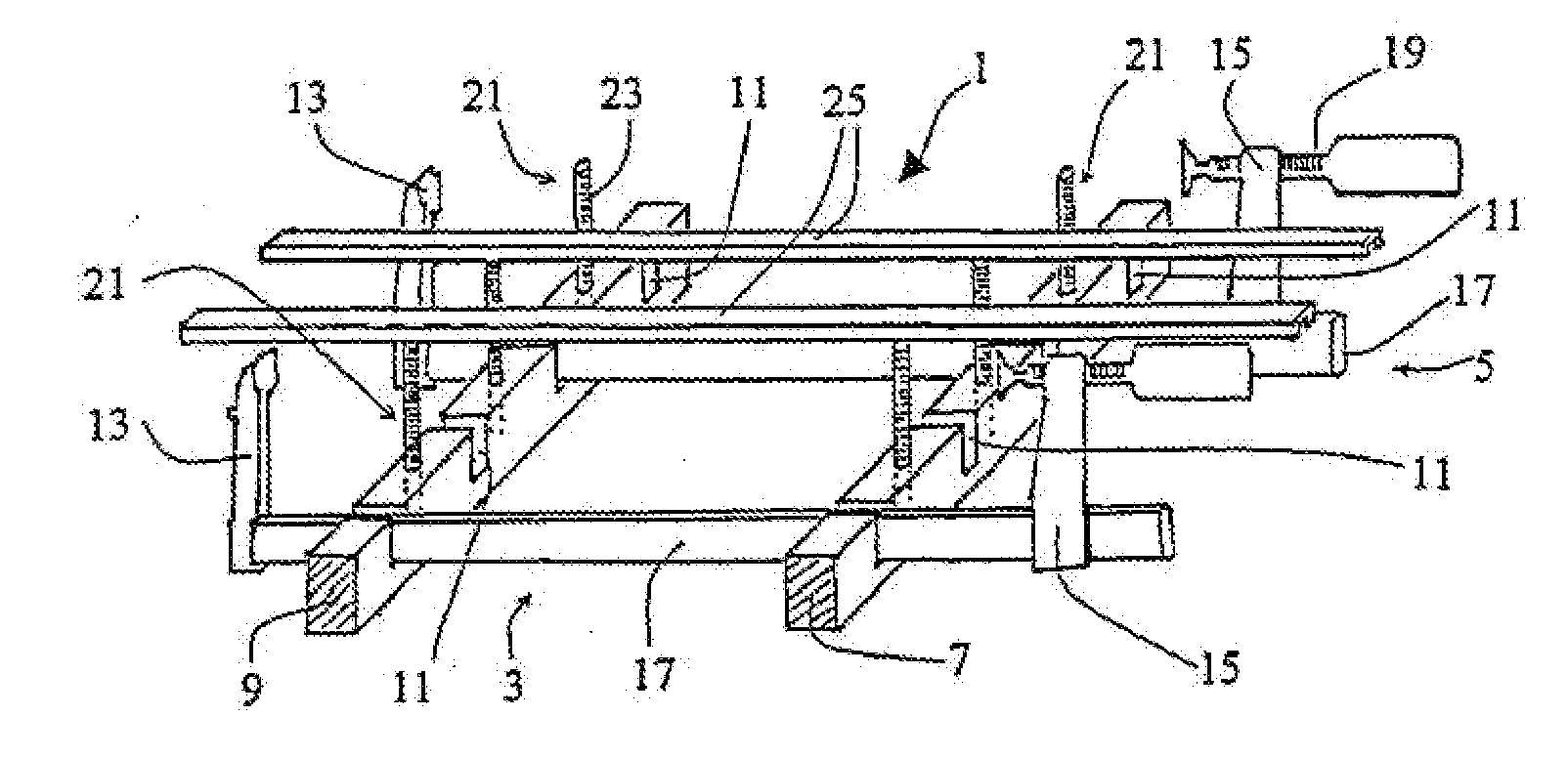
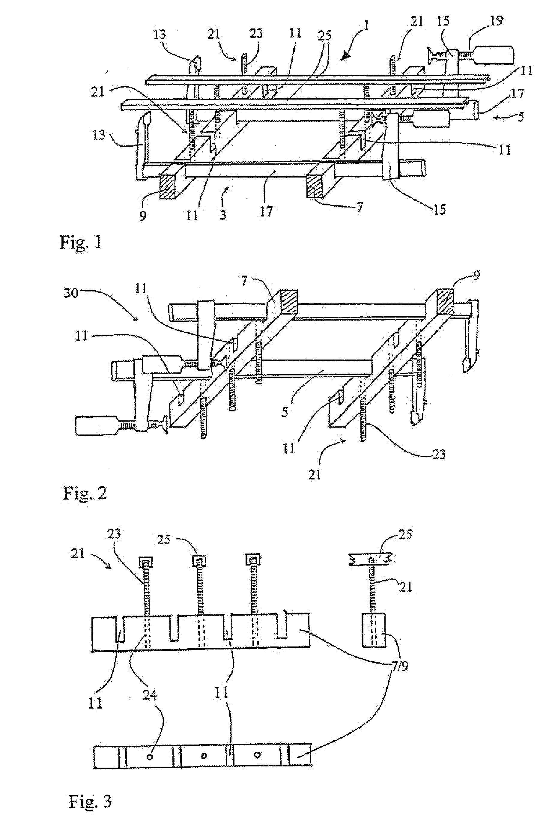
[0044]FIG. 1 shows a perspective view of a lower clamping arrangement 1 according to a A first and a second screw clamp 3, 5 are connected to a first and a second transverse beam 7, 9 parallel and spaced apart from each other. In the transverse beams 7, 9, grooves 11 pass transversely to the length axis, each disposed at the transverse beam in spaced apart manner. The first and the second screw clamp 3, 5 are inserted with their rails 17 in respectively one groove of the first and the second transverse beam 7, 9. In the illustrated examples, the screw clamps 3, 5 are loosely inserted into the grooves 11, however, it can also be provided that fixing members of elements, for example a screw inserted next to the grooves 11, are provided for the grooves 11, by means of which the screw clamps 3, 5 are clamped in the grooves 11. The screw clamps 3, 5 are inserted into the grooves 11 such that respectively one fixed clamping arm 13 and one displaceable clamping arm 15 of the screw clamps ...
second embodiment
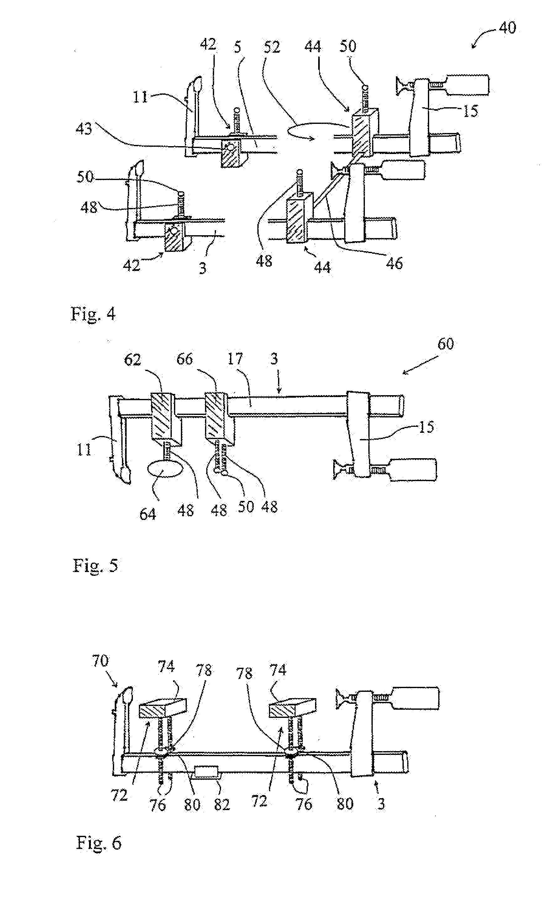
[0049]FIG. 4 shows a perspective view of a lower clamping arrangement 40 according to a A first adjusting slider 42 and a second adjusting slider 44 is associated with each screw clamp 3, 5. As indicated in FIG. 4, the first adjusting sliders 42 are fixed to the rail 17 of the screw clamp 3, 5 by means of a screw 43. At the same time, the first adjusting sliders 42 with their bottom side serve as a support base for vertical alignment of the clamping arms 13, 15. The second adjusting sliders 44 are connected to each other through a connecting rod 46. The second adjusting sliders 44 can also be fixedly connected to the rail 17 by fixing means or loosely sit there and be displaced over the rail in the clamping direction. Advantageously, the length of the connecting rod 46 is variable such that the distance between the screw clamps 3, 5 is variable. By providing several connecting rods 46 and several second adjusting sliders 44, more than two screw clamps 3, 5 can be consecutively disp...
fifth embodiment
[0057]FIG. 9 shows a clamping arrangement on a work plate 100 and a work bench, respectively, or a multifunction table. The work plate 100 has holes 102 in a matrix having predetermined spacing and is part of the clamping arrangement in this embodiment, wherein the work plate 100 replaces the transverse elements 7, 9 of the previous embodiments. The threaded bolts 23 are guided through the holes 102 and their height above the work plate 100 is achieved by rotating the knurled screws 104. The diameter of the knurled screws 104 is significantly greater than the diameter of the holes 102 such that by seating the knurled screws 104 a vertical alignment of the bolts 23 results. The clamps (here only the first clamp 3 is exemplary shown) are vertically aligned by bases 106. Advantageously, the bases 106 have pins protruding downwards such that the bases can be inserted into the holes 102 by the pins.
[0058] Further aspects not yet described or further developments or alternatives for singl...
PUM
 Abstract
Description
Claims
Application Information
 - R&D Engineer
- R&D Manager
- IP Professional
- Industry Leading Data Capabilities
- Powerful AI technology
- Patent DNA Extraction
Browse by: Latest US Patents, China's latest patents, Technical Efficacy Thesaurus, Application Domain, Technology Topic.
© 2024 PatSnap. All rights reserved.Legal|Privacy policy|Modern Slavery Act Transparency Statement|Sitemap