
Gravure plate, method for forming light-emitting layer or hole-injection layer using the same, and organic light-emitting device

Inactive Publication Date: 2007-01-11
DAI NIPPON PRINTING CO LTD
View PDF7 Cites 20 Cited by
  • Summary
  • Abstract
  • Description
  • Claims
  • Application Information

AI Technical Summary

Benefits of technology

[0018] The present invention has been accomplished in the light of the above-described problems in the prior art. Accordingly, an object of the present invention is to provide a gravure plate useful in forming a light-emitting layer or a hole-injection layer in the desired pattern, having a great and uniform thickness; a method for forming a light-emitting layer or a hole-injection layer, using the gravure plate; and a highly-reliable organic light-emitting device excellent in display performance.
[0048] By the use of the gravure plate of the present invention, it is possible to form a light-emitting layer and a hole-injection layer that are uniform in thickness and have the desired thicknesses.
[0049] The method for forming a light-emitting layer according to the present invention makes it possible to form a light-emitting layer having a uniform thickness as great as 70 nm or more, and, moreover, form light-emitting layers that emit light of different colors, each light-emitting layer in the desired pattern. The method for forming a hole-injection layer according to the present invention makes it possible to form a hole-injection layer in the desired pattern, having a uniform thickness as great as 50 nm or more. Moreover, these methods of the invention make it possible to form a light-emitting layer and a hole-injection layer on a flexible substrate such as a resin film substrate. In addition, the blanket for use in the methods of the invention is excellent in plate wear and can contribute to the reduction of the cost of production of an organic light-emitting device.
[0050] Further, the light-emitting layer and the hole-injection layer of an organic light-emitting device of the present invention have thicknesses that are great and uniform because they are formed by the methods of the present invention, so that the luminance and the emission efficiency of the light-emitting device layer at the time of emission of light are high. Therefore, the organic light-emitting device of the invention is excellent in display performance and reliability.

Problems solved by technology

However, the above-described conventional methods for forming a light-emitting layer or a hole-injection layer, using a gravure plate or an intaglio printing plate, use ink having relatively high viscosity, so that when filling recesses in an intaglio printing plate with the ink by the use of a doctor blade, part of the ink tends to be left on the non-recessed portions of the printing plate without being scraped off with the doctor blade, or the ink layer formed tends to be non-uniform in thickness.
It has thus been difficult to form, by the conventional methods, light-emitting layers uniform in thickness.
Therefore, it has so far been difficult to form a light-emitting layer with a thickness as great as 70 nm or more and a hole-injection layer with a thickness as great as 50 nm or more.
Further, since the ink readily penetrates the silicone blanket, the conventional methods have been disadvantageous in that the light-emitting layer or hole-injection layer formed has a roughened surface and that the plate wear of the silicone blanket is impaired.
However, to form a light-emitting layer or a hole-injection layer in the desired pattern by spin coating, it is necessary to combine a spin coating process with a photolithographic process, so that the whole process gets complicated.
In addition, there has been a problem that the ink is used only at a decreased efficiency.
However, unless the fluidity, the surface tension, or the like of the ink to be jetted is well controlled, it has been difficult to form a light-emitting layer or a hole-injection layer uniform in thickness.
Further, a conventional organic light-emitting device for use as a full-color or area-color display has been insufficient in luminance and emission efficiency because the thickness of its light-emitting layer or hole-injection layer is non-uniform or not satisfactorily great as described above.
Such a device has had limitations to improvement in display performance and has not been highly reliable.

Method used


Image

  • Gravure plate, method for forming light-emitting layer or hole-injection layer using the same, and organic light-emitting device
  • Gravure plate, method for forming light-emitting layer or hole-injection layer using the same, and organic light-emitting device
  • Gravure plate, method for forming light-emitting layer or hole-injection layer using the same, and organic light-emitting device

Examples


example 1

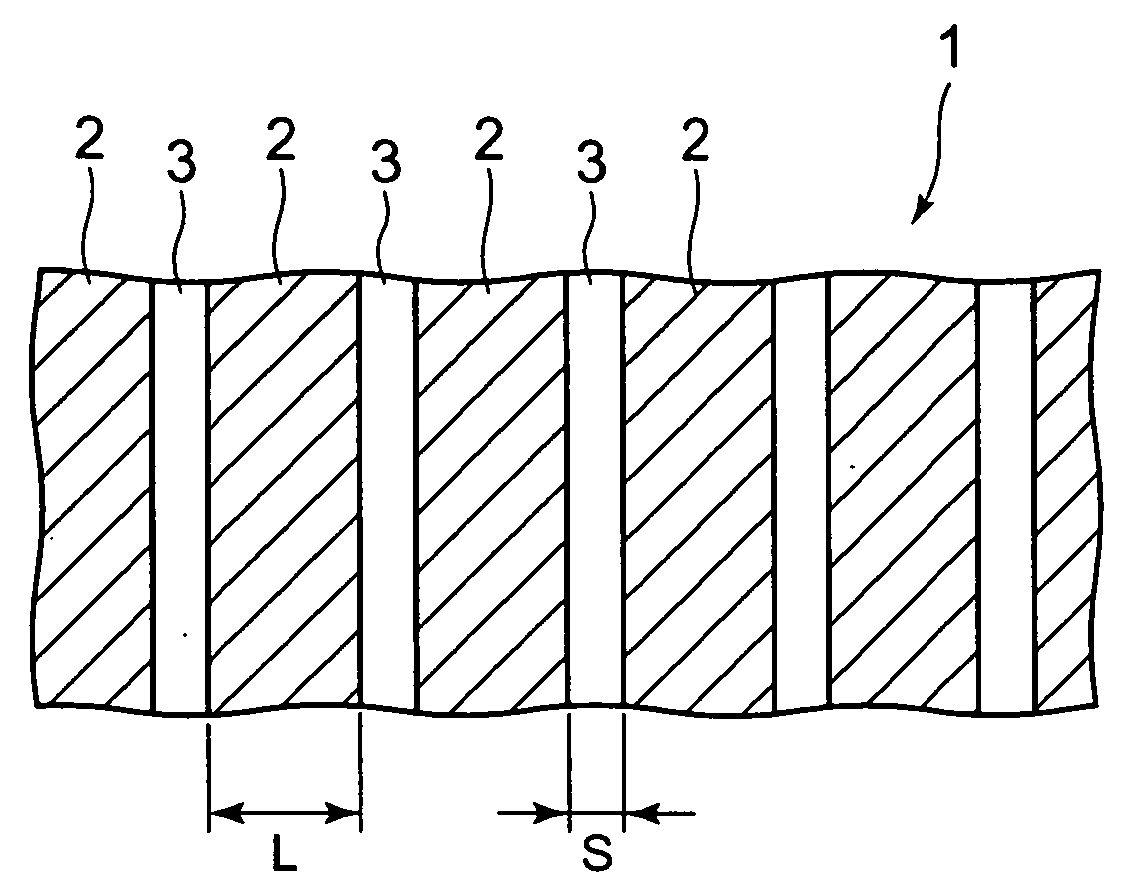
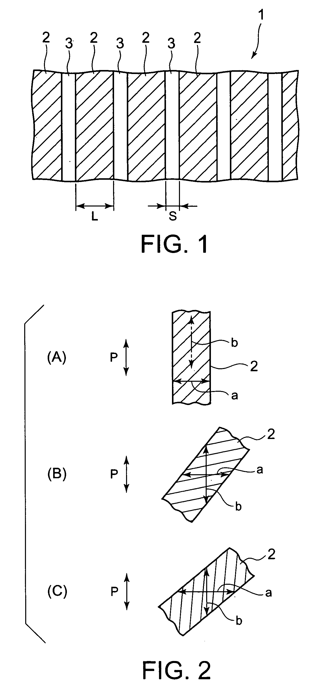
[0176] Ten different gravure plates (G1-A to G1-J) in the form of sheets, having cells in the shape of stripes (the depth of the cells: 35 μm) extending in the direction of printing (the direction of rotation of the blanket cylinder), were prepared, in which the length L of the cell portions and the length S of the non-cell portions were changed over a range of 10 to 500 μm and a range of 2 to 500 μm, respectively, to vary, as shown in Table 1, the proportion of the length L of the cell portions to the length S of the non-cell portions S, L / S. The effective width of the gravure plates was 50 mm.

[0177] A red-light-emitting-layer-forming ink composition A1 having the following formulation was prepared. The coefficient of viscosity of this ink composition A1 (ink temperature: 23° C.), measured at a shear rate of 100 sec−1 with a viscoelasticity meter Model MCR301 manufactured by Physica Corp. in the steady flow mode, was 80 cP. Further, using a tension meter Model CBVP-Z manufactured ...

example 2

[0194] Nine different gravure plates (G2-A to G2-I) in the form of sheets, having cells in the shape of stripes (the depth of the cells: 35 μm) extending in the direction of printing (the direction of rotation of the blanket cylinder), were prepared, in which the length L of the cell portions and the length S of the non-cell portions were varied as shown in Table 2 so that the proportion of the length L of the cell portions to the length S of the non-cell portions, L / S, fell in the range of 1 to 10. The effective width of the gravure plates was 50 mm.

[0195] Red light-emitting layers and hole-injection layers were formed in the same manner as in Example 1, except that the above-described gravure plates were used instead of the gravure plates used in Example 1.

[0196] Printability at the time the red light-emitting layers were formed by the use of the gravure plates different in both the length L of the cell portions and the length S of the non-cell portions, and printability at the ...

example 3

[0198] Seven different gravure plates (G3-A to G3-G) in the form of sheets, varying in depth as shown in Table 3, having cells in the shape of stripes extending in the direction of printing (the direction of rotation of the blanket cylinder), were prepared, in which the length L of the cell portions and the length S of the non-cell portions S were made 120 μm and 30 μm, respectively (the proportion L / S was 4). The effective width of the gravure plates was 50 mm.

[0199] Red light-emitting layers and hole-injection layers were formed in the same manner as in Example 1, except that the above-described gravure plates were used instead of the gravure plates used in Example 1.

[0200] Printability at the time the red light-emitting layers were formed by the use of the gravure plates different in depth, and printability at the time the hole-injection layers were formed by the use of these gravure plates were evaluated. Further, the percentage of variations in thickness [(maximum thickness−m...


PUM


Abstract

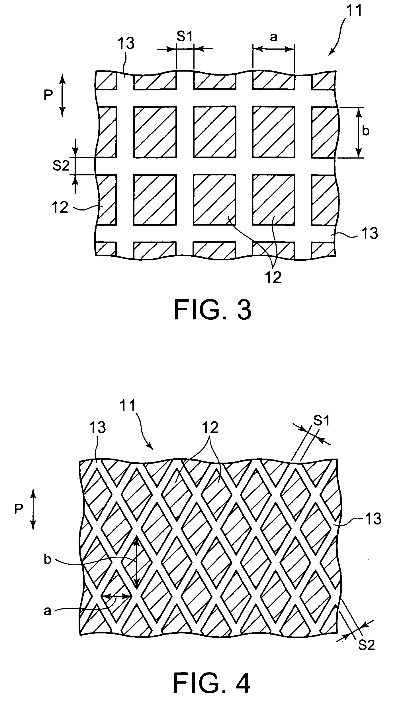
A gravure plate useful in forming a light-emitting layer and / or a hole-injection layer of an organic light-emitting device has a plurality of cells in the shape of stripes, and non-cell portions between the cells. The proportion of the width b of each cell measured in the direction of printing to the width a of each cell measured in the direction perpendicular to the direction of printing, b / a, is 0.6 or more, and the proportion of the length L of each cell to the length S of each non-cell portion, L / S, is from 0.8 to 100. The length L of each cell is from 10 to 500 μm, the length S of each non-cell portion is from 2 to 500 μm, and the depth of the gravure plate is from 20 to 200 μm.

Description

BACKGROUND OF THE INVENTION [0001] 1. Field of the Invention [0002] The present invention relates to a gravure plate useful in forming, by gravure offset printing, a light-emitting layer and a hole-injection layer, components of an organic light-emitting device, to a method for forming a light-emitting layer or a hole-injection layer, and to an organic light-emitting device. [0003] 2. Background Art [0004] Organic electroluminescence (EL) devices (organic light-emitting devices) have the following advantages: they are excellent in visibility because they are self-luminous; they are wholly solid displays unlike liquid crystal displays; they are scarcely affected by changes in temperature; they have great viewing angles; and so forth. In recent years, they have come to be put into practical use as organic light-emitting devices such as full-color displays, area-color displays, and illuminations. [0005] Organic light-emitting devices have light-emitting layers, and organic light-emitti...

Claims


Application Information

Patent Timeline
IPC IPC(8): H01J1/62
CPCB41M1/10H05B33/10H01L51/56H01L51/0004H10K71/13H10K71/40H10K71/164H05B33/14H10K71/00
Inventor TAKEDA, TOSHIHIKOMORITO, SHIGERUKOBAYASHI, MASARUSHIROGANE, HIROYUKI
Owner DAI NIPPON PRINTING CO LTD
Learn More