Aluminum support for planographic printing plate and planographic printing plate precursor

Inactive Publication Date: 2019-03-28
FUJIFILM CORP
View PDF1 Cites 0 Cited by
  • Summary
  • Abstract
  • Description
  • Claims
  • Application Information

AI Technical Summary

Benefits of technology

The invention provides an aluminum support and a planographic printing plate precursor that can be used to produce a plate precursor for a planographic printing plate that has excellent plate wear resistance and on-machine developability. This is achieved by setting an average depth of pits on the surface of the aluminum support within a predetermined range and using an aluminum support that satisfies a specific surface area-increase rate.

Problems solved by technology

Meanwhile, generally, on-machine developability and plate wear resistance have a trade-off relationship, and it is difficult to improve both performances.
As a result of studies regarding a variety of performances of plate precursors for planographic printing and planographic printing plates obtained using a well-known support for a planographic printing plate of the related art described in JP2004-114324A, JP2004-114677A, and the like, the present inventors found that the characteristics such as on-machine developability and plate wear resistance satisfy the loose demanded characteristics of the related art, but fail to satisfy currently-demanded characteristics and cannot always be satisfied in a practical sense.

Method used


Image

  • Aluminum support for planographic printing plate and planographic printing plate precursor
  • Aluminum support for planographic printing plate and planographic printing plate precursor
  • Aluminum support for planographic printing plate and planographic printing plate precursor

Examples


example 1

[0271][Production of Aluminum Support for Planographic Printing Plate]

[0272]In order to remove a rolling oil on the surface of a 0.3 mm-thick aluminum plate (material: JIS A 1050), a defatting treatment was carried out at 50° C. for 30 seconds using an aqueous solution of 10% by mass of sodium aluminate.

[0273]After that, the surface of the aluminum plate was grained using three nylon braided brushes having a hair diameter of 0.3 mm and a water suspension of pumice having a median diameter of 25 μm (specific weight: 1.1 g / cm3) and well washed with water.

[0274]Next, the aluminum plate was immersed in an aqueous solution of 25% by mass of sodium hydroxide (45° C.) for nine seconds to carry out etching, washed with water, then, further immersed in an aqueous solution of 20% by mass of nitric acid at 60° C. for 10 seconds, and washed with water. The amount of the grained surface etched was approximately 3 g / m2.

[0275]

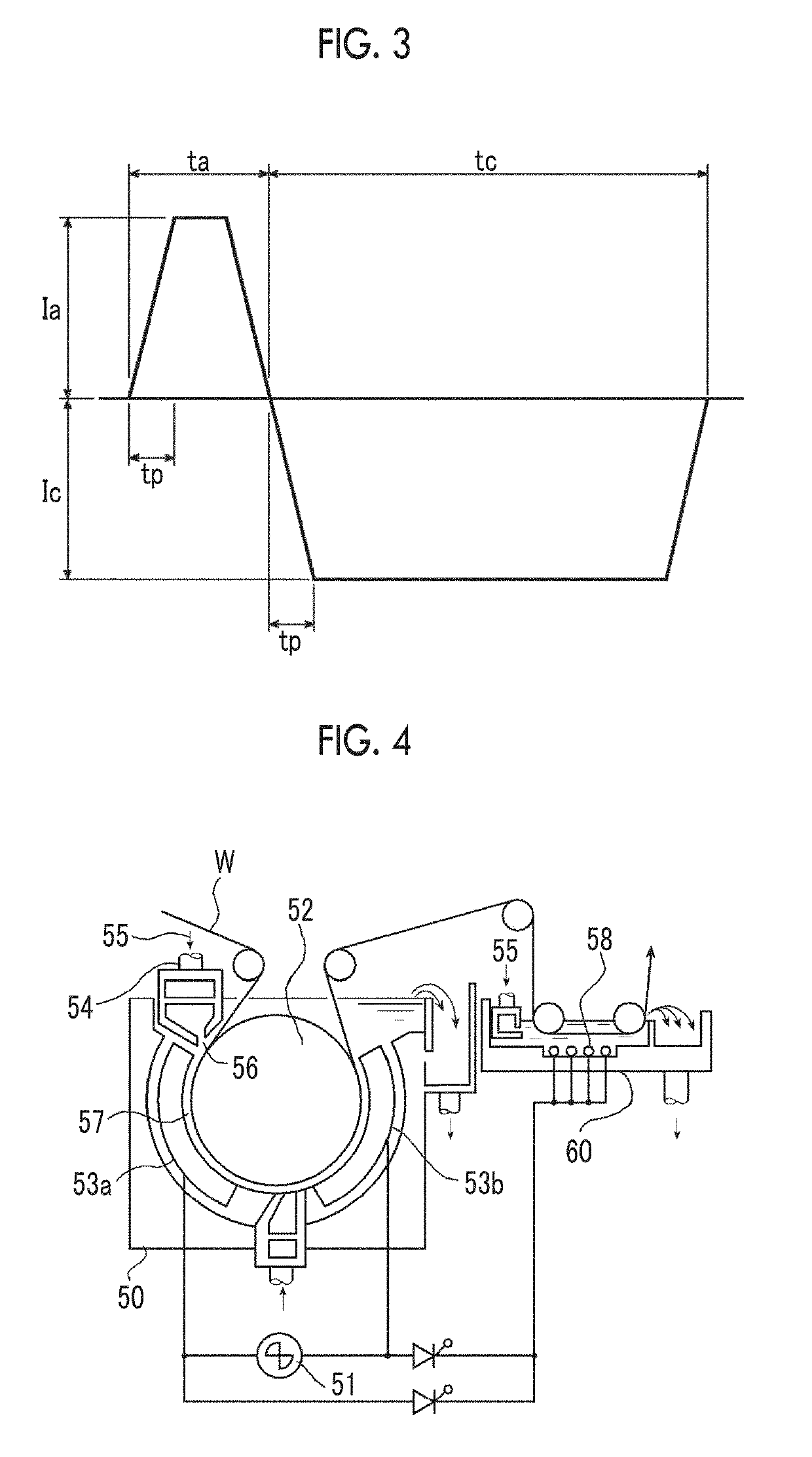
[0276]Next, an electrochemical roughening treatment was continuously car...

examples 13 to 19

[0298]Aluminum supports for a planographic printing plate and planographic printing plate precursors were produced using the same method as in Example 1 except for the presence or absence of the undercoat layer and the use of a compound not having a repeating unit having a phosphoric acid group in the structure of the compound for an undercoat layer (1) instead of the compound for an undercoat layer (1) as shown in Table 1.

[0299]For the aluminum supports for a planographic printing plate produced in Examples 1 to 19 and Comparative Examples 1 to 4, the average value of the surface area-increase rates ΔSSEM (%), the average value of the pit depths ΔhSEM (nm), and the respective values of L*, a*, and b* in the L*a*b* color space were measured using the above-described method. The results are shown in Table 1.

[0300][Evaluation]

[0301]

[0302]The obtained planographic printing plate precursor was exposed using Fujifilm's Luxel PLATESETTER T-6000III equipped with an infrared semiconductor l...


PUM


Abstract

An object of the invention is to provide an aluminum support for a planographic printing plate and a planographic printing plate precursor which can be used to obtain a plate precursor for a planographic printing plate that is excellent in terms of plate wear resistance in the case of being used to produce a planographic printing plate and exhibits excellent on-machine developability. In an aluminum support for a planographic printing plate of the embodiment of the invention, an average value of surface area-increase rates ΔSSEM (%) is 200% or more, and an average value of pit depths ΔhSEM (nm) is 400 nm or less.

Description

CROSS-REFERENCE TO RELATED APPLICATIONS[0001]This application is a Continuation of PCT International Application No. PCT / JP2017 / 018502 filed on May 17, 2017, which claims priority under 35 U.S.C. § 119(a) to Japanese Patent Application No. 2016-107035 filed on May 30, 2016. The above application is hereby expressly incorporated by reference, in its entirety, into the present application.BACKGROUND OF THE INVENTION1. Field of the Invention[0002]The present invention relates to an aluminum support for a planographic printing plate and a planographic printing plate precursor.2. Description of the Related Art[0003]A planographic printing method is a printing method using the fact that water and oil essentially do not mix together, and, on a printing plate surface of a planographic printing plate that is used in the planographic printing method, a region that stores water and thus repels oil-based ink (hereinafter, this region will be referred to as the “non-image area”) and a region tha...

Claims


Application Information

Patent Timeline
IPC IPC(8): B41N1/08B41N3/08G03F7/11G03F7/20G03F7/115G03F7/32
CPCB41N1/083B41N3/08G03F7/11G03F7/20G03F7/115G03F7/32G03F7/00G03F7/09B41N3/034B41C2210/04B41C2210/08
Inventor KATABAMI, SHIGEHIRONISHINO, GO
Owner FUJIFILM CORP
Why Eureka
Try Eureka