Lithographic printing process

a technology of lithographic printing and printing plate, which is applied in the field of lithographic printing process, can solve the problems of image-recording layer of presensitized plate used in the conventional process that is not fixed, image cannot be recorded with ir laser, and weaken the cohesion of the layer, etc., and achieves excellent plate wear.

Inactive Publication Date: 2010-12-14
FUJIFILM CORP
View PDF22 Cites 0 Cited by
  • Summary
  • Abstract
  • Description
  • Claims
  • Application Information

AI Technical Summary

Benefits of technology

[0030]When the ethylenically unsaturated polymerizable compound having adherence to the hydrophilic support is exposed to light, the ethylenically unsaturated bond reacts to harden the compound together with the ethylenically unsaturated polymerizable compound having no adherence to the hydrophilic support. At the same time, the polymerized compounds firmly adhere on the hydrophilic support. As a result, a lithographic printing plate produced according to the present invention has excellent plate wear.
[0031]The present invention makes it possible to print many sheets clearly with a lithographic printing plate produced with a practical amount of energy.

Problems solved by technology

Before removed mechanically with the rollers or cylinder, it may be beforehand swollen with dampening water or solvent of ink to weaken the cohesion of the layer or the adhesion onto the support.
Even after exposed to the light, an image-recording layer of presensitized plate used in the conventional process is not fixed.
Therefore, if a conventional presensitized plate is used in the press development, it is necessary to adopt a complicated process comprising, for example, a step of keeping the exposed presensitized plate under completely light-shielded condition or at a constant temperature until the plate is installed in a printing machine.
However, since most practical photosensitive recording materials are sensitive to visible light of 760 nm or shorter, images cannot be recorded with IR lasers.
The above process, in which the fine particles are simply aggregated by heat to form an image, is very suitable for the press development, but the formed image in relief (namely, the image-forming layer remaining in the image-forming area) has such poor durability (poor adhesion onto the support) that the plate wear is insufficient.
However, even so, from the practical viewpoint, they are still too unsatisfactory for the press development and have too poor plate wear and too low polymerization efficiency (sensitivity) to use practically.

Method used


Image

  • Lithographic printing process
  • Lithographic printing process
  • Lithographic printing process

Examples


example 1

Preparation of Aluminum Support

[0203]An aluminum plate (material: 1050) having 0.3 mm thickness was subjected to oil-removing treatment with 10 wt. % aqueous solution of sodium aluminate at 50° C. for 30 seconds to remove rolling oil on the surface. The surface of the plate was then grained with three brushes having nylon bristles of 0.3 mm diameter and with a suspension of pumice (median size: 25 μm) in water (specific gravity: 1.1 g / cm3), and washed with water. The plate was then immersed for etching in 25% aqueous solution of sodium hydroxide at 45° C. for 9 seconds, washed with water, immersed again in 20% nitric acid at 60° C. for 20 seconds, and washed with water. In this way, the surface was etched in an amount of approx. 3 g / m2.

[0204]The plate was then successively roughened electrochemically with alternating current of 60 Hz. The electrolyte used in the treatment was 1 wt. % aqueous solution of nitric acid (containing aluminum ion in 0.5 wt. %) at 50° C. In the treatment, a...

examples 2-5

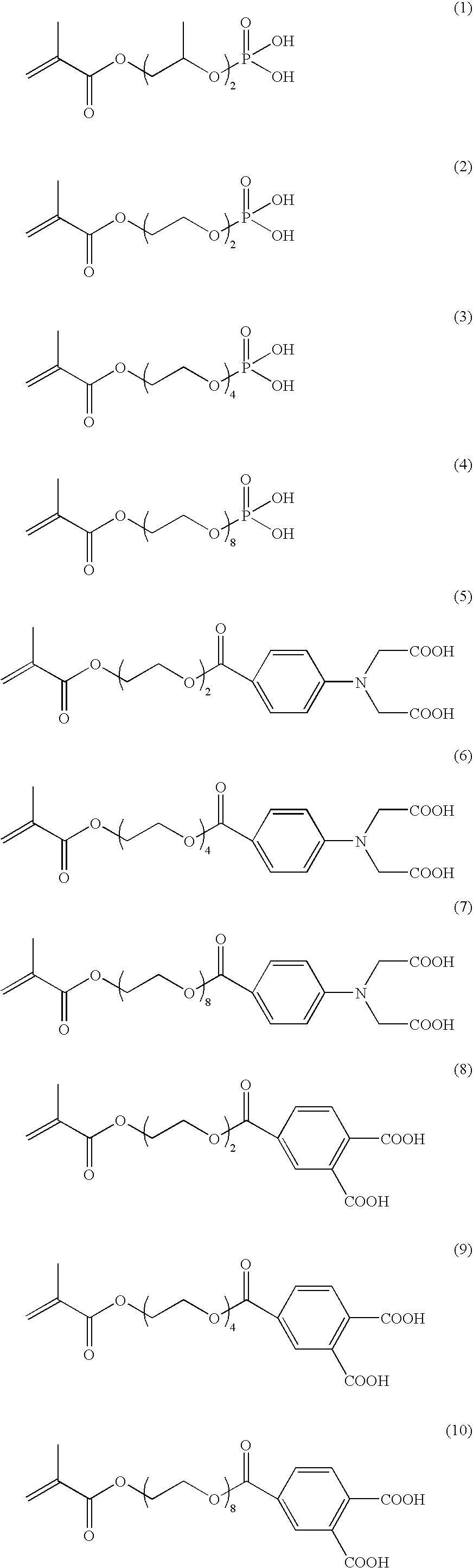
[0212]The procedure of Example 1 was repeated except that the compound (4), (13), (17) or (33) was used in place of the compound (9), to produce a presensitized lithographic printing plate.

example 6

[0214]The coating solution consisting of the following components was prepared and spread with a bar coater to coat the aluminum support, and then dried in an oven at 100° C. for 60 seconds to form the image-recording layer in the amount of 1.0 g / m2 (dry condition). Thus, a presensitized lithographic printing plate was produced.

[0215]

Coating solution for image-recording layerThe following infrared-absorbing dye (2)0.05gThe following polymerization initiator (1)0.2gThe following binder polymer (1) having the average molecular weight of 80,0000.5gThe compound (8)0.05gIsocyanulic acid ethyleneoxide-modified triacrylate(NK ester M-315, from Shin-Nakamura Chemical Co., Ltd.)1.0gThe fluorine-containing surface active agent (1) in Example 10.1gMethyl ethyl ketone18.0gInfrared-absorbing dye (2)Polymerization initiator (1)Binder polymer (1)


PUM

PropertyMeasurementUnit
pKaaaaaaaaaaa
wavelengthaaaaaaaaaa
wavelength rangeaaaaaaaaaa

Abstract

A lithographic printing process which comprises the steps of: imagewise scanning with a laser a presensitized lithographic plate which comprises a hydrophilic support and an image-recording layer containing a polymerization initiator, an ethylenically unsaturated polymerizable compound having no adherence to the hydrophilic support, and an ethylenically unsaturated polymerizable compound having adherence to the hydrophilic support and a molecular structure comprising a polyoxyalkylene group to polymerize the ethylenically unsaturated polymerizable compounds within the exposed area; removing the image-recording layer within the unexposed area from the lithographic plate mounted on a cylinder of a printing press; and then printing an image with the lithographic plate mounted on the cylinder of the printing press. A presensitized lithographic plate is also disclosed.

Description

FIELD OF THE INVENTION[0001]The present invention relates to a lithographic printing process. The invention also relates to a presensitized lithographic process.BACKGROUND OF THE INVENTION[0002]A lithographic printing plate generally comprises a hydrophobic imaging area, which receives oily ink in printing, and a hydrophilic non-imaging area (ink-repelling area), which receives dampening water. The lithographic printing process is essentially based on the fact that water is incompatible with oily ink. In the process, the ink is put on a surface of the plate unevenly so that only the imaging area may receive it, and then transferred onto an object (e.g., paper) to be printed.[0003]For producing a lithographic printing plate, a presensitized printing plate (PS plate) comprising a hydrophilic support and a thereon-provided hydrophobic photosensitive resin layer (image-recording layer) has been conventionally used. The PS plate is masked and exposed to light through an original image (e...

Claims


Application Information

Patent Timeline
Patent Type & Authority Patents(United States)
IPC IPC(8): G03C1/00G03C1/72G03C7/00B41F7/00B41C1/10G03F7/004B41N1/14G03F7/00G03F7/085
CPCB41C1/1008B41C1/1016B41C2201/02B41C2201/04B41C2201/06B41C2201/10B41C2201/14B41C2210/04B41C2210/08B41C2210/20B41C2210/22B41C2210/24
Inventor MAKINO, NAONORIINNO, TOSHIFUMI
Owner FUJIFILM CORP
Why Eureka
Try Eureka