Method and apparatus for remotely monitoring a site

a remote monitoring and site technology, applied in the field of remote monitoring sites, can solve the problems of large number of video surveillance cameras, large quantities of data that cannot be easily transmitted to remote monitoring sites in real-time, and system has not achieved the widespread use associated with binary off/on systems

Inactive Publication Date: 2007-01-11
NETTALON SECURITY SYST
View PDF17 Cites 315 Cited by
  • Summary
  • Abstract
  • Description
  • Claims
  • Application Information

AI Technical Summary

Benefits of technology

[0009] The present invention is directed to providing systems and methods for remotely monitoring sites to provide real-time information that can readily distinguish false alarms from real ones and that can identify and track the location of an alarm and / or its cause with substantial precision. In exemplary embodiments, monitoring capabilities such as intrusion / fire detection and tracking capabilities can be implemented through the use of multistate indicators in a novel interface that permits information to be transmitted using standard network protocols from a remote site to a monitoring station in real-time over preexisting communication network transmission pathways (e.g. wire, fiber optic, wireless and satellite). Communications can thereby be established between a centrally located host monitoring station and a separate security / fire panel deployed in each of the buildings to be remotely monitored.
[0018] Embodiments of the present invention can provide primary visual alarm status reporting that gives the monitoring authority (e.g., a user) the ability to identify the precise location of an intrusion and / or fire, and to distinguish false alarms from real ones. Multiple state, or multistate, indications are provided to represent a sensor. For example, in various embodiments, each sensor may be identified as being: (1) currently in alarm; (2) currently in alarm and acknowledged by a monitor; (3) recently in alarm; (4) not in alarm; (5) disabled; or (6) non-reporting. With these multistate indications, the movements of an intruder or fire can be tracked, and yet the location of the intruder / fire can still be identified with a great deal of precision. This additional tracking ability gives police and firemen a tactical advantage at the scene as they know the location of the subject / fire and can track any subsequent movements as they close in order to make an arrest and / or fight the fire.

Problems solved by technology

However, a large number of video surveillance cameras is cost prohibitive, and they generate large quantities of data that cannot be easily transmitted to remote monitoring sites in real-time.
Accordingly, these systems have not achieved the widespread use associated with binary off / on systems.
Even when a large number of sensors is used to increase the resolution of alert information, the use of binary on / off indicators prohibits any meaningful ability to track an intruder's movement through the building and yet still be able to resolve the current location of the intruder.
In addition, known binary off / on systems typically cannot distinguish whether an alarm is real (i.e., genuine) or false.
When police arrive on the scene of a building where an alarm was tripped, they do not know whether the alarm is real or false, and they have little or no information about what is inside the building.
Substantial time and money is wasted when police respond to large numbers of false alarms.
Even when the alarms are valid, police often expect another false alarm and can be taken by surprise.
The same drawbacks exist for known fire monitoring and surveillance systems.
In addition, existing fire monitoring and surveillance systems do not provide real-time information to the first responders that would otherwise enable them to initiate life safety procedures under conditions of more nearly complete information.

Method used


Image

  • Method and apparatus for remotely monitoring a site
  • Method and apparatus for remotely monitoring a site
  • Method and apparatus for remotely monitoring a site

Examples


Embodiment Construction

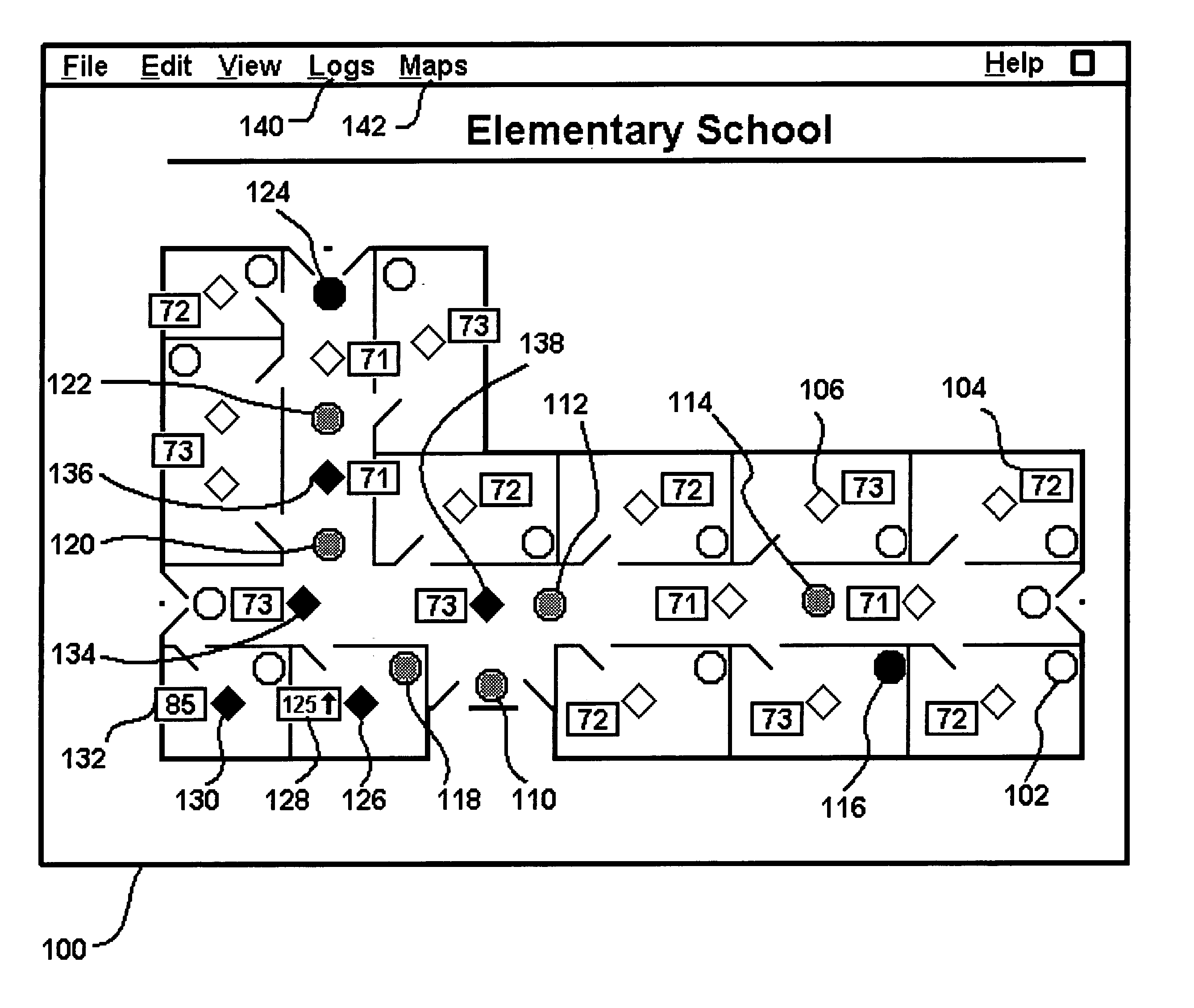
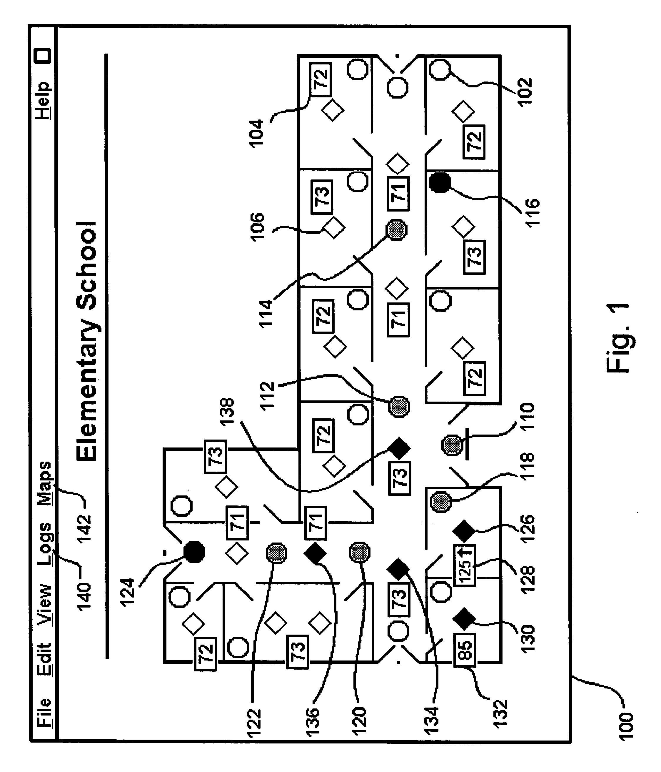
[0039] 1. Functional Overview. Before describing details of an exemplary system for implementing an exemplary embodiment of the present invention, an overview of the invention will be provided using one exemplary display of information that is provided at a supervisory monitoring system's graphical user interface in accordance with the present invention. Referring to FIG. 1, a graphical user interface provides a screen display 100 of a particular floor plan in a building being monitored for intrusion and fire detection. In the FIG. 1 example, a graphical user interface included in the supervisory monitoring system is displaying a building floor plan for an elementary school with its alarm points, and illustrates a two-person intrusion with a related fire (arson) in progress. In this black / white rendition, points not in alarm are white circles 102 indicating intrusion detectors, environmental monitors 104 (in this example, air temperature) indicating reasonably expected room temperat...


PUM


Abstract

The present invention is directed to providing systems and methods for remotely monitoring sites to provide real-time information which can readily permit distinguishing false alarms, and which can identify and track the precise location of an alarm. In embodiments, monitoring capabilities such as intrusion / fire detection and tracking capabilities, can be implemented through the use of multistate indicators in an interface which permits information to be transmitted using standard network protocols from a remote site to a monitoring station in near real-time. In embodiments, communications can be handed from the centrally located host monitoring station to a mobile monitoring station (for example, a laptop computer in a responding vehicle, such as a police or fire vehicle). Additional embodiments include the measurement of environmental parameters such as temperature, carbon monoxide and differential air pressure to detect, monitor and manage a fire event. These measurements along with selected controllable output devices deployed in a space, such as sprinkler control valves and individually or zoned sprinkler heads, are used to initiate and control fire suppression technology both locally and remotely. For instance, a system of the present invention may detect a fire and cause a sprinkler system to disburse water in a facility.

Description

CROSS-REFERENCE TO RELATED APPLICATIONS [0001] This application is a continuation-in-part of U.S. application Ser. No. 11 / 140,925, filed Jun. 1, 2005, now U.S. Pat. No. 6,917,288, which is a continuation of U.S. application Ser. No. 10 / 140,439, which is a continuation-in-part of U.S. application Ser. No. 10 / 069,788, filed Feb. 28, 2002, now U.S. Pat. No. 6,972,676, which was filed as a United States national stage application under 35 U.S.C. § 371 of Patent Cooperation Treaty application serial number PCT / US00 / 23974, filed Sep. 1, 2000, which claims priority under 35 U.S.C. § 119 to U.S. application Ser. No. 09 / 387,496, filed Sep. 1, 1999, now U.S. Pat. No. 6,281,790. Each of the above-identified applications and patents is incorporated herein by reference in its entirety.FIELD OF THE INVENTION [0002] The present invention relates generally to monitoring a remote site. More particularly, the present invention is directed to monitoring a remote site by providing real-time or substant...

Claims


Application Information

Patent Timeline
Patent Type & Authority Applications(United States)
IPC IPC(8): G08B29/00G08B13/196G08B25/14
CPCA62C99/00G08B25/14G08B13/19608G08B13/19645G08B13/19656G08B13/19682G08B13/19684G08B13/19691G08B13/19697G08B13/22G08B17/00G08B25/001G08B25/002G08B25/009G08B25/10G08B13/19G08B25/007
Inventor KIMMEL, DAVID E.JONES, DONALD R.DUBOIS, RONALDCOLIN, DANIEL C.
Owner NETTALON SECURITY SYST
Why Eureka
Try Eureka