Power tool movement monitor and operating system

a technology of power tools and operating systems, applied in the direction of process and machine control, metal sawing accessories, instruments, etc., can solve the problems of power hand tools, nail guns, increasing construction and industrial accidents, and stationary power tools, such as drill presses or shop machines used in manufacturing, often vibrating or chattering after extended us

Inactive Publication Date: 2007-01-11
THE BOEING CO
View PDF19 Cites 51 Cited by
  • Summary
  • Abstract
  • Description
  • Claims
  • Application Information

AI Technical Summary

Benefits of technology

[0006] In accordance with systems consistent with the present invention, a power tool movement monitor system is provided. The power tool movement monitor system includes a first accelerometer operatively configured to sense movement along a first axis of a power tool and a first high pass filter operatively connected to the output of the first accelerometer. The first high pass filter has an output and a cutoff frequency corresponding to a predetermined acceleration limit capable of being output by the first accelerometer. The power tool movement monitor system also includes a logic circuit operatively configured to generate a warning signal when the first high pass filter outputs a signal having a frequency equaling or exceeding the cutoff frequency of the first high pass filter.
[0007] In accordance with systems consistent with the present invention, another implementation of a power tool movement monitor system is provided. The power tool movement monitor system includes a first accelerometer operatively configured to sense movement along a first axis of a power tool and a first low pass filter operatively connected to the ...

Problems solved by technology

Construction and industrial accidents involving power hand tools, such as nail guns, are increasing.
Typically, nail gun injuries result from the improper movement of the nail gun, such as swinging the nail gun laterally into the user's leg when walking or dropping the nail gun onto the floor causing a nail to be shot out of the gun, potentially causing damage to property or hitting people n...

Method used


Image

  • Power tool movement monitor and operating system
  • Power tool movement monitor and operating system
  • Power tool movement monitor and operating system

Examples


Embodiment Construction

[0023] Reference will now be made in detail to an implementation in accordance with methods, systems, and products consistent with the present invention as illustrated in the accompanying drawings. The same reference numbers may be used throughout the drawings and the following description to refer to the same or like parts.

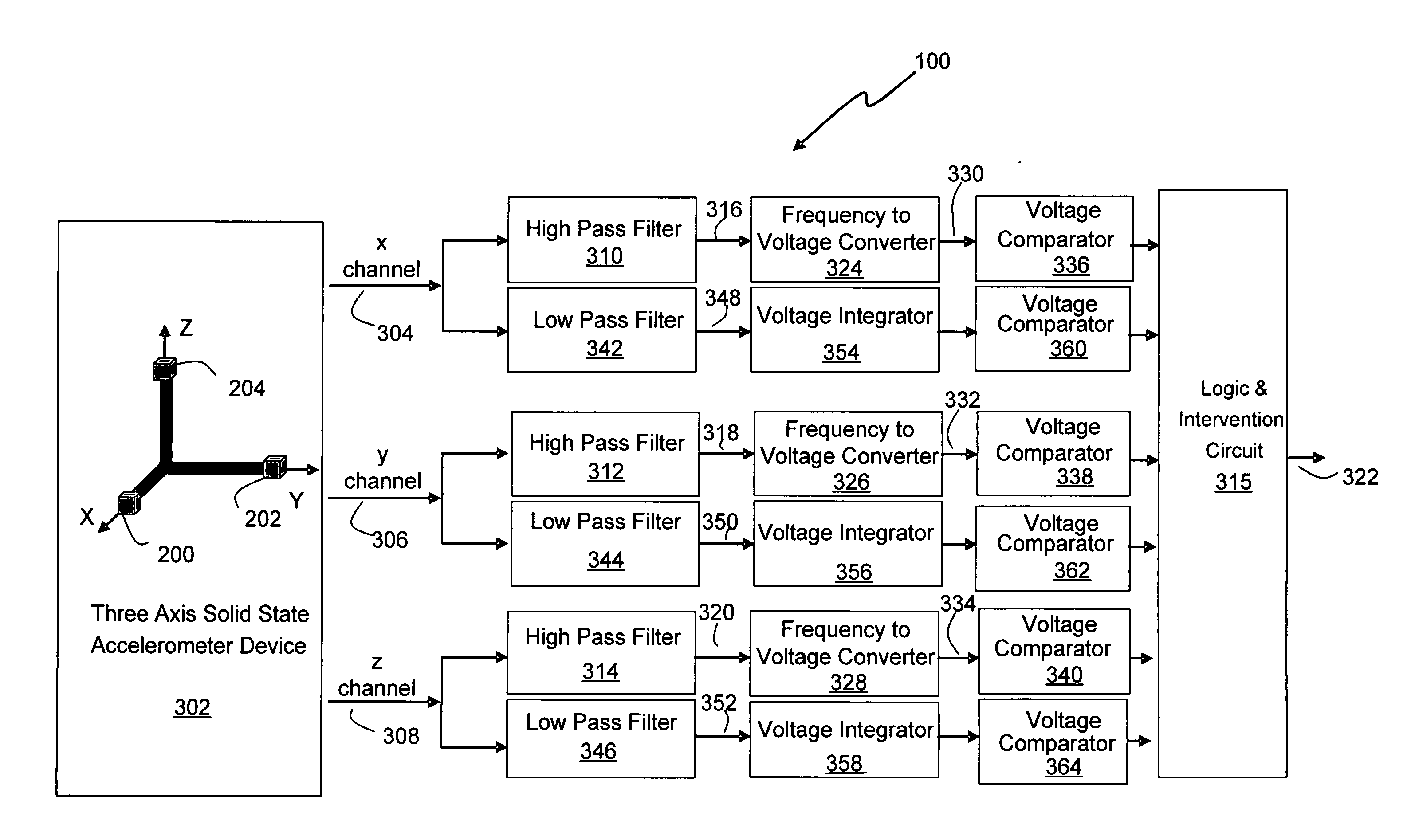
[0024] In accordance with methods and systems consistent with the present invention, a power tool movement monitor system is provided that is able to disrupt the action or operation of the tool when the power tool movement monitor system determines that movement of the tool exceeds a predetermined limit (e.g., a predetermined acceleration limit or a predetermined velocity limit), which may be predefined for the tool and its field of use. As discussed below, the predetermined acceleration limits and the predetermined velocity limits may derived for each orthogonal axis of the power tool to define an operating regime the power tool so the movement monitor system m...


PUM

PropertyMeasurementUnit
Currentaaaaaaaaaa
Electric potential / voltageaaaaaaaaaa
Frequencyaaaaaaaaaa

Abstract

A power tool movement monitor system including a first accelerometer operatively configured to sense movement along a first axis of a power tool and a first high pass filter operatively connected to the output of the first accelerometer. The first high pass filter has an output and a cutoff frequency corresponding to a predetermined acceleration limit capable of being output by the first accelerometer. The power tool movement system further includes a logic circuit operatively configured to generate a warning signal when the first high pass filter outputs a signal having a frequency equaling or exceeding the cutoff frequency of the first high pass filter.

Description

BACKGROUND OF THE INVENTION [0001] The present invention relates to power tools, and, more particularly, to methods and systems for monitoring the movement of a power tool to detect non-operational condition. [0002] Construction and industrial accidents involving power hand tools, such as nail guns, are increasing. Currently, eight percent of all industrial accidents involve the use of hand tools. In the construction industry, injuries involving nail guns account for more than half of worker compensation claims. Typically, nail gun injuries result from the improper movement of the nail gun, such as swinging the nail gun laterally into the user's leg when walking or dropping the nail gun onto the floor causing a nail to be shot out of the gun, potentially causing damage to property or hitting people nearby. [0003] Furthermore, stationary power tools, such as drill presses or shop machines used in manufacturing, often vibrate or chatter after extended use. In addition, controlled syst...

Claims


Application Information

Patent Timeline
IPC IPC(8): G08B21/00
CPCB25C7/00
Inventor GOSSETT, TIMOTHY J.LADWIG, DONALD R.SPENO, FRANK G.
Owner THE BOEING CO
Why Eureka
Try Eureka