Image sensor and method thereof

a technology of image sensor and image, applied in the field of semiconductor devices, can solve the problem that it is difficult for the charge transfer unit to transfer all the accumulated charges stored, and achieve the effect of optimizing or improving the charge transfer and improving the charge transfer

Active Publication Date: 2007-01-11
SAMSUNG ELECTRONICS CO LTD
View PDF4 Cites 7 Cited by
  • Summary
  • Abstract
  • Description
  • Claims
  • Application Information

AI Technical Summary

Benefits of technology

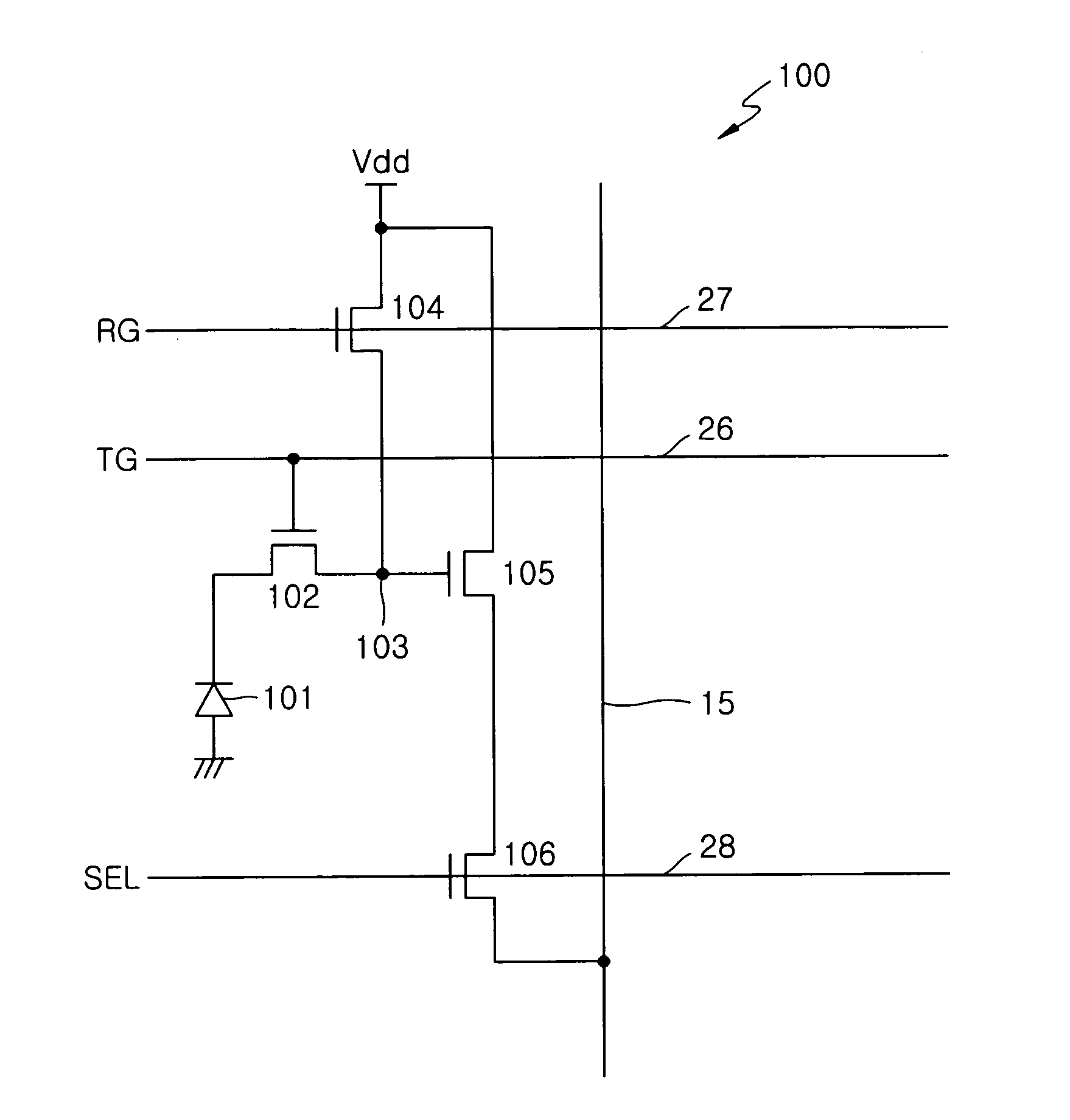
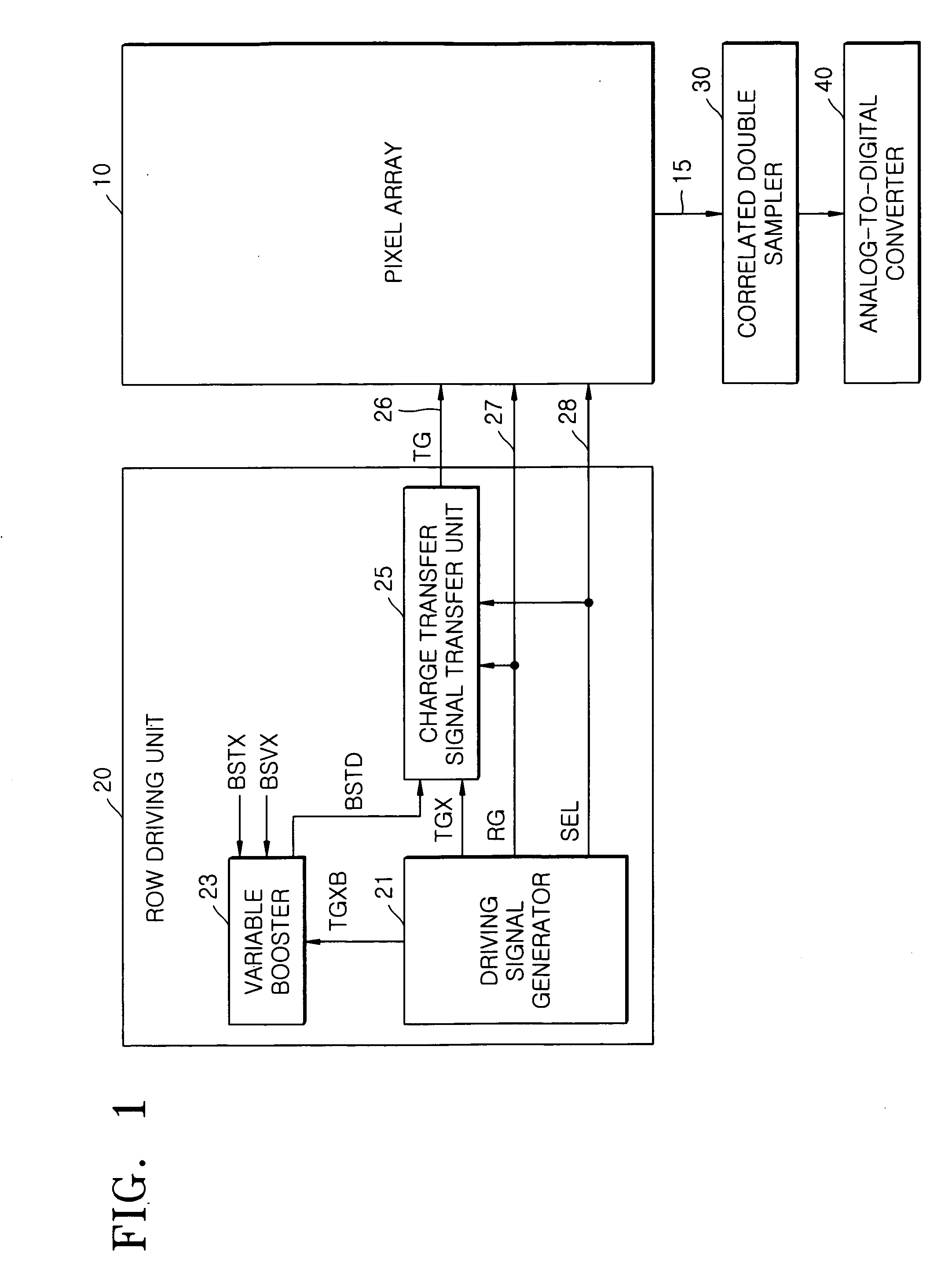
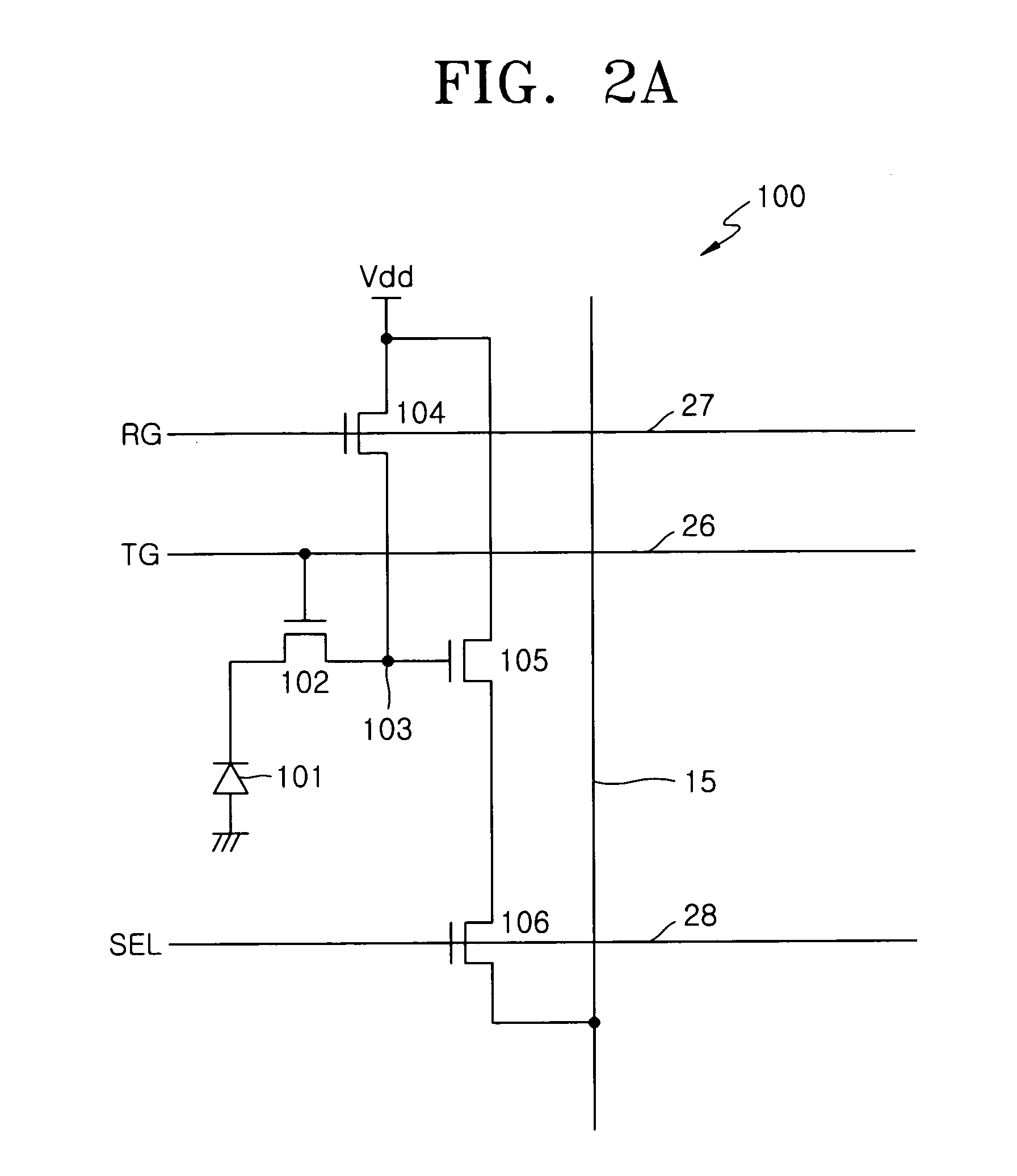
[0009] An example embodiment of the present invention is directed to an image sensor, including a pixel array including a plurality of unit pixels, each of the plurality of unit pixels having a charge transfer unit for transferring charges accumulated in an optoelectronic converter to a charge detector via a charge transfer driving signal and a row driving unit generating a boosted voltage, the boosted voltage set to a boosted voltage level higher than a power voltage level, the boosted voltage selectively boosted in response to a boosting voltage variable control signal, and selectively applying the charge transfer driving signal to the pixel array.
[0010] Another example embodiment of the present invention is directed to a method of improving a charge transfer in an image device, including selectively adjusting a voltage level of a charge transfer driving voltage and transferring the charge transfer driving voltage to a charge transfer unit for controlling an operation of the charge transfer unit.
[0011] Another example embodiment of the present invention may be directed to a complementary metal oxide semiconductor (CMOS) image sensor capable of optimizing or improving a charge transfer by varying a charge transfer driving voltage.

Problems solved by technology

As image sensors are fabricated at reduces sizes, it may become more difficult for the charge transfer unit to transfer all of the accumulated charges stored in the photodiode to the charge detector.

Method used


Image

  • Image sensor and method thereof
  • Image sensor and method thereof
  • Image sensor and method thereof

Examples


Embodiment Construction

[0021] Detailed illustrative example embodiments of the present invention are disclosed herein. However, specific structural and functional details disclosed herein are merely representative for purposes of describing example embodiments of the present invention. Example embodiments of the present invention may, however, be embodied in many alternate forms and should not be construed as limited to the embodiments set forth herein.

[0022] Accordingly, while example embodiments of the invention are susceptible to various modifications and alternative forms, specific embodiments thereof are shown by way of example in the drawings and will herein be described in detail. It should be understood, however, that there is no intent to limit example embodiments of the invention to the particular forms disclosed, but conversely, example embodiments of the invention are to cover all modifications, equivalents, and alternatives falling within the spirit and scope of the invention. Like numbers m...


PUM


Abstract

An image sensor and method thereof. In an example, the image sensor, may include a pixel array including a plurality of unit pixels, each of the plurality of unit pixels having a charge transfer unit for transferring charges accumulated in an optoelectronic converter to a charge detector via a charge transfer driving signal. The example image sensor may further include a row driving unit generating a boosted voltage, the boosted voltage set to a boosted voltage level higher than a power voltage level, the boosted voltage selectively boosted in response to a boosting voltage variable control signal. The row driving unit may selectively apply the charge transfer driving signal to the pixel array. In another example, the method may include selectively adjusting a voltage level of a charge transfer driving voltage and transferring the charge transfer driving voltage to a charge transfer unit for controlling an operation of the charge transfer unit.

Description

PRIORITY STATEMENT [0001] This application claims the benefit of priority under 35 USC § 119 from Korean Patent Application No. 10-2005-0061242, filed on Jul. 7, 2005, in the Korean Intellectual Property Office, the contents of which is incorporated herein by reference in its entirety. BACKGROUND OF THE INVENTION [0002] 1. Field of the Invention [0003] Example embodiments of the present invention relate generally to a semiconductor device and method thereof, and more particularly to an image sensor and method thereof. [0004] 2. Description of the Related Art [0005] Image sensors may be devices capable of converting optical images into electric signals. Image sensors may be deployed in a variety of device types, including but not limited to a digital camera, a camcorder, a personal computer system, a game machine, a security camera, a medical micro-camera, a robot, etc. [0006] Conventional image sensors may be classified as charge coupled device (CCD) image sensors or complementary m...

Claims


Application Information

Patent Timeline
Patent Type & Authority Applications(United States)
IPC IPC(8): H04N5/335H04N5/374
CPCH04N5/335H04N3/1512H04N25/00H04N25/74H04N25/77H04N25/75
Inventor ROH, JAE-SEOB
Owner SAMSUNG ELECTRONICS CO LTD
Why Eureka
Try Eureka