Apparatus and methods for determining overlay of structures having rotational or mirror symmetry

a technology of rotational or mirror symmetry and overlay, applied in semiconductor/solid-state device testing/measurement, semiconductor/solid-state device details, instruments, etc., can solve the problems of limiting requirements, and affecting the placement of the same cos

Inactive Publication Date: 2007-01-11
KLA TENCOR TECH CORP
View PDF14 Cites 55 Cited by
  • Summary
  • Abstract
  • Description
  • Claims
  • Application Information

AI Technical Summary

Benefits of technology

[0018] These and other features and advantages of the present invention will be presented in more detail in the following...

Problems solved by technology

However, these requirements may be too restrictive under certain conditions.
For example, space may be limited on the wafer and a target having x and y structures (or first and second layer structures) ...

Method used


Image

  • Apparatus and methods for determining overlay of structures having rotational or mirror symmetry
  • Apparatus and methods for determining overlay of structures having rotational or mirror symmetry
  • Apparatus and methods for determining overlay of structures having rotational or mirror symmetry

Examples


Embodiment Construction

[0028] Reference will now be made in detail to a specific embodiment of the invention. An example of this embodiment is illustrated in the accompanying drawings. While the invention will be described in conjunction with this specific embodiment, it will be understood that it is not intended to limit the invention to one embodiment. On the contrary, it is intended to cover alternatives, modifications, and equivalents as may be included within the spirit and scope of the invention as defined by the appended claims. In the following description, numerous specific details are set forth in order to provide a thorough understanding of the present invention. The present invention may be practiced without some or all of these specific details. In other instances, well known process operations have not been described in detail in order not to unnecessarily obscure the present invention.

[0029] In general, the present invention provides semiconductor targets for determining an overlay error b...


PUM


Abstract

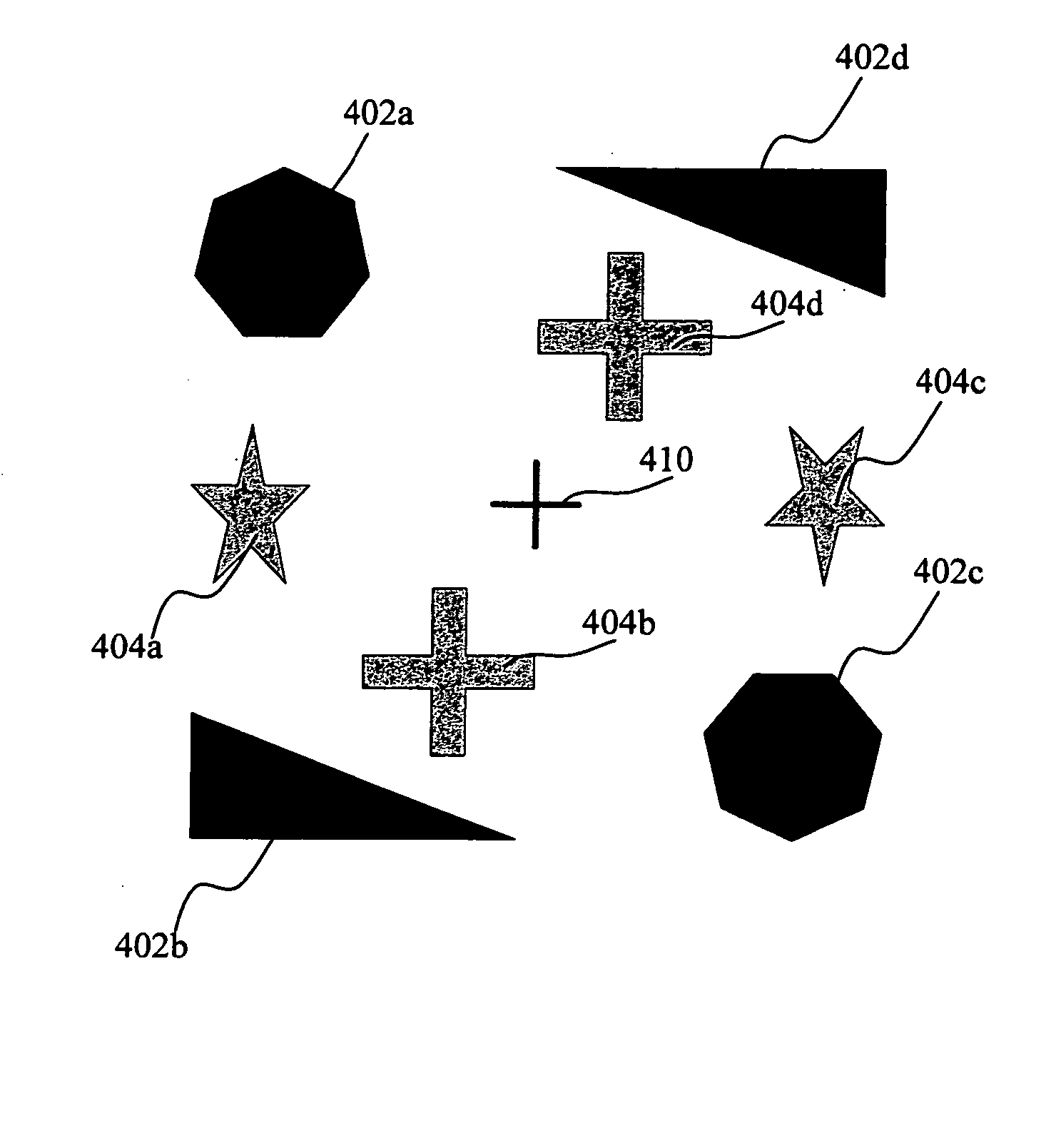
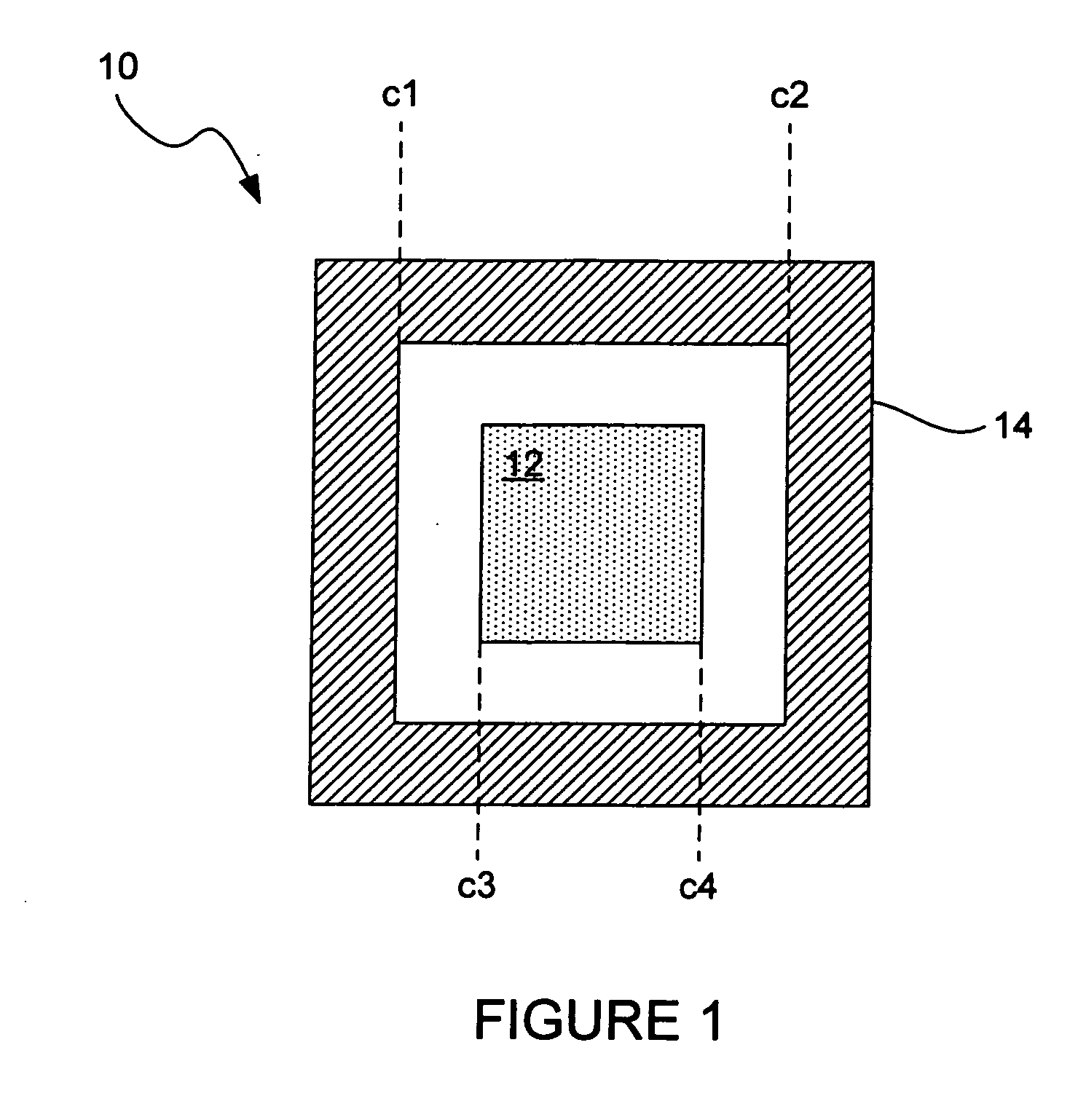
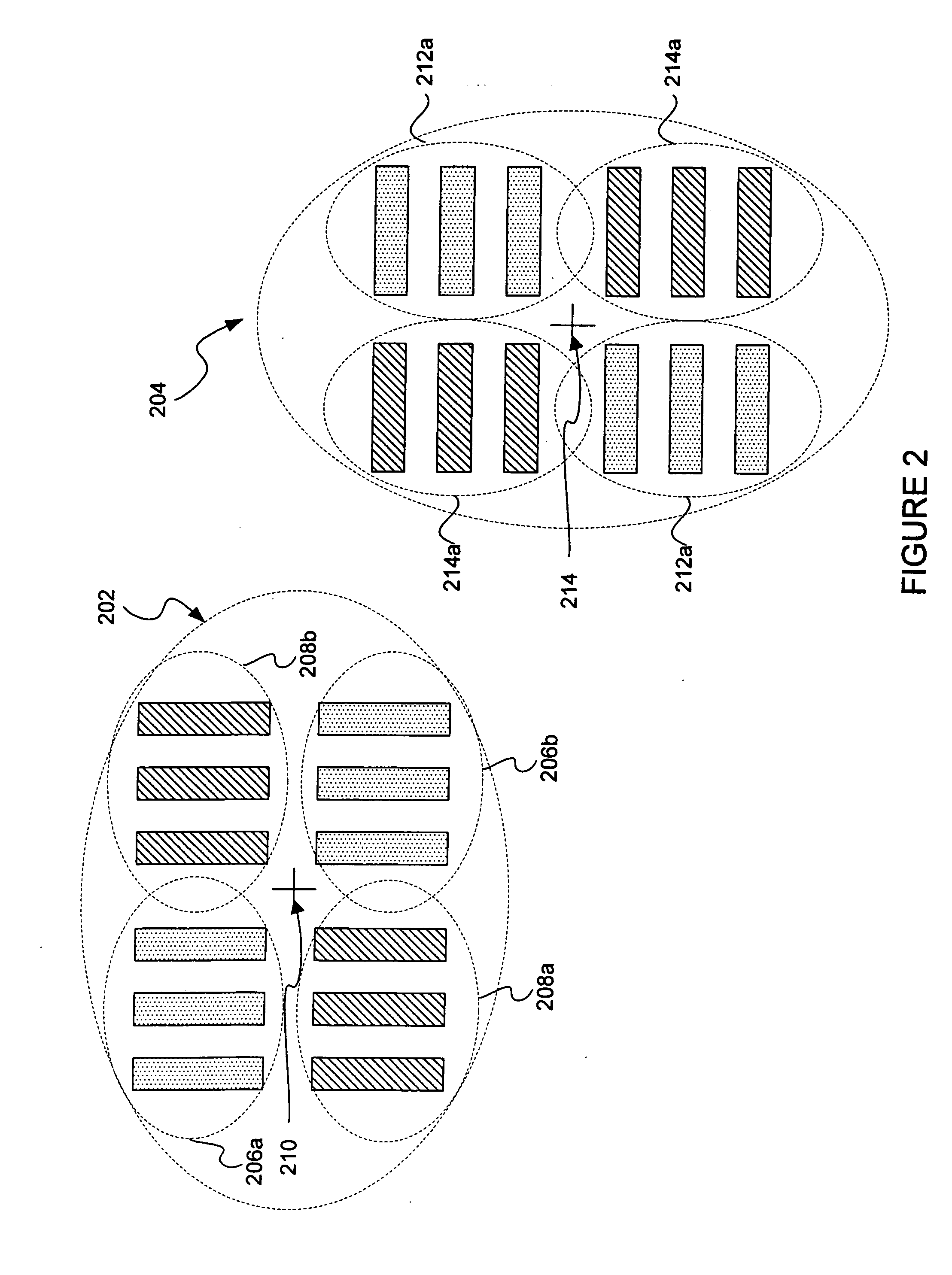
Disclosed are overlay targets having flexible symmetry characteristics and metrology techniques for measuring the overlay error between two or more successive layers of such targets. In one embodiment, a target includes structures for measuring overlay error (or a shift) in both the x and y direction, wherein the x structures have a different center of symmetry (COS) than the y structures. In another embodiment, one of the x and y structures is invariant with a 180° rotation and the other one of the x and y structures has a mirror symmetry. In one aspect, the x and y structures together are variant with a 180° rotation. In yet another example, a target for measuring overlay in the x and/or y direction includes structures on a first layer having a 180 symmetry and structures on a second layer having mirror symmetry. In another embodiment, a target for determining overlay in the x and/or y direction includes structures on a first layer and structures on a second layer, wherein the structures on the first layer have a COS that is offset by a known amount from the COS of the structures on the second layer. In a specific implementation, any of the disclosed target embodiments may take the form of device structures. In a use case, device structures that have an inherent 180° rotational symmetry or a mirror symmetry in each of the first and second layers are used to measure overlay in a first layer and a second layer. Techniques for imaging targets with flexible symmetry characteristics and analyzing the acquired images to determine overlay or alignment error are disclosed.

Description

CROSS REFERENCE TO RELATED PATENT APPLICATION [0001] This application claims priority of U.S. Provisional Patent Application No. 60 / 698,535 (Attorney Docket No. KLA1P149P), entitled APPARATUS AND METHODS FOR DETERMINING OVERLAY STRUCTURES HAVING ROATIONAL OR MIRROR SYMMETRY, filed 11 Jul. 2005 by Mark Ghinovker, which application is incorporated herein by reference in its entirety for all purposes.BACKGROUND OF THE INVENTION [0002] The present invention relates generally to overlay measurement techniques, which are used in semiconductor manufacturing processes. More specifically, the present invention relates to techniques for measuring alignment error between different layers or different patterns on the same layer of a semiconductor wafer stack. [0003] The measurement of overlay error between successive patterned layers on a wafer is one of the most critical process control techniques used in the manufacturing of integrated circuits and devices. Overlay accuracy generally pertains...

Claims


Application Information

Patent Timeline
IPC IPC(8): G01B11/00
CPCY10S438/975G03F7/70633H01L21/682H01L21/68H01L23/544G01N21/4785G01N21/9501G01B11/272
Inventor GHINOVKER, MARK
Owner KLA TENCOR TECH CORP
Why Eureka
Try Eureka