Optical return-to-zero phase-shift keying with improved transmitters

a phase shift keying and optical technology, applied in electromagnetic transmission, electrical equipment, transmission, etc., can solve the problems of reducing the applicability of metropolitan and local area networks, high costs of each optical modulator,

Inactive Publication Date: 2007-01-11
ZITELLI MARIO
View PDF2 Cites 31 Cited by
  • Summary
  • Abstract
  • Description
  • Claims
  • Application Information

AI Technical Summary

Benefits of technology

[0012] In another aspect of the present invention, two SM-RZ-DQPSK are polarization-time interleaved at the transmitter, the two signals having half-bit delay and orthogonal polarization between them. The obtained polarization-interleaved (PI) signal, referred in the following as PI-SM-RZ-DQPSK, requires 4 input tributaries with bit rate R=1 / TB at the transmitter, and is characterized by a transport capacity of 4×R. (Gbit / s) and improved spectral efficiency.
[0014] In the said aspects of the present invention, the generated signal spectral efficiency may overcome the value of 1.6 bit / s / Hz without the need of a polarization controller at the receiver. Signal at 10 Gbitis according to one aspect of the invention is able to reach a 300 km transmission distance of uncompensated standard monomodal fiber (SMF).

Problems solved by technology

The complexity of the proposed transmitters, and the high costs for each optical modulator reduce their applicability to metropolitan and local area networks, where cost-effective devices are a primary requisite.

Method used


Image

  • Optical return-to-zero phase-shift keying with improved transmitters
  • Optical return-to-zero phase-shift keying with improved transmitters
  • Optical return-to-zero phase-shift keying with improved transmitters

Examples


first embodiment

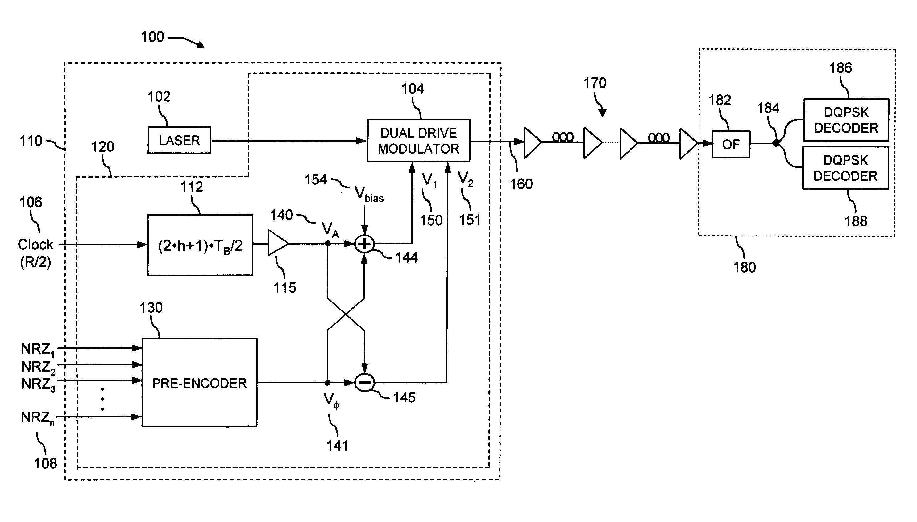
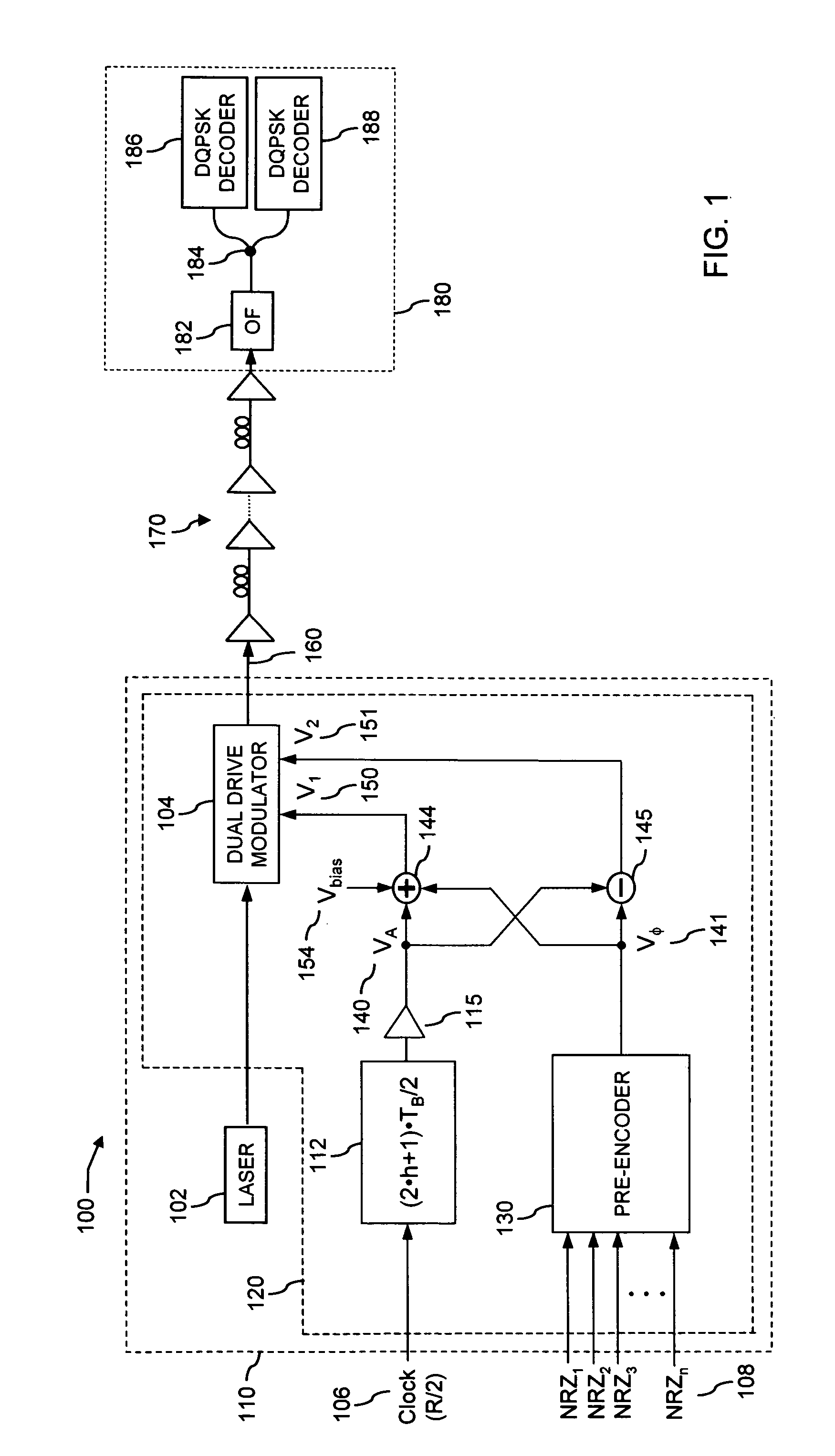
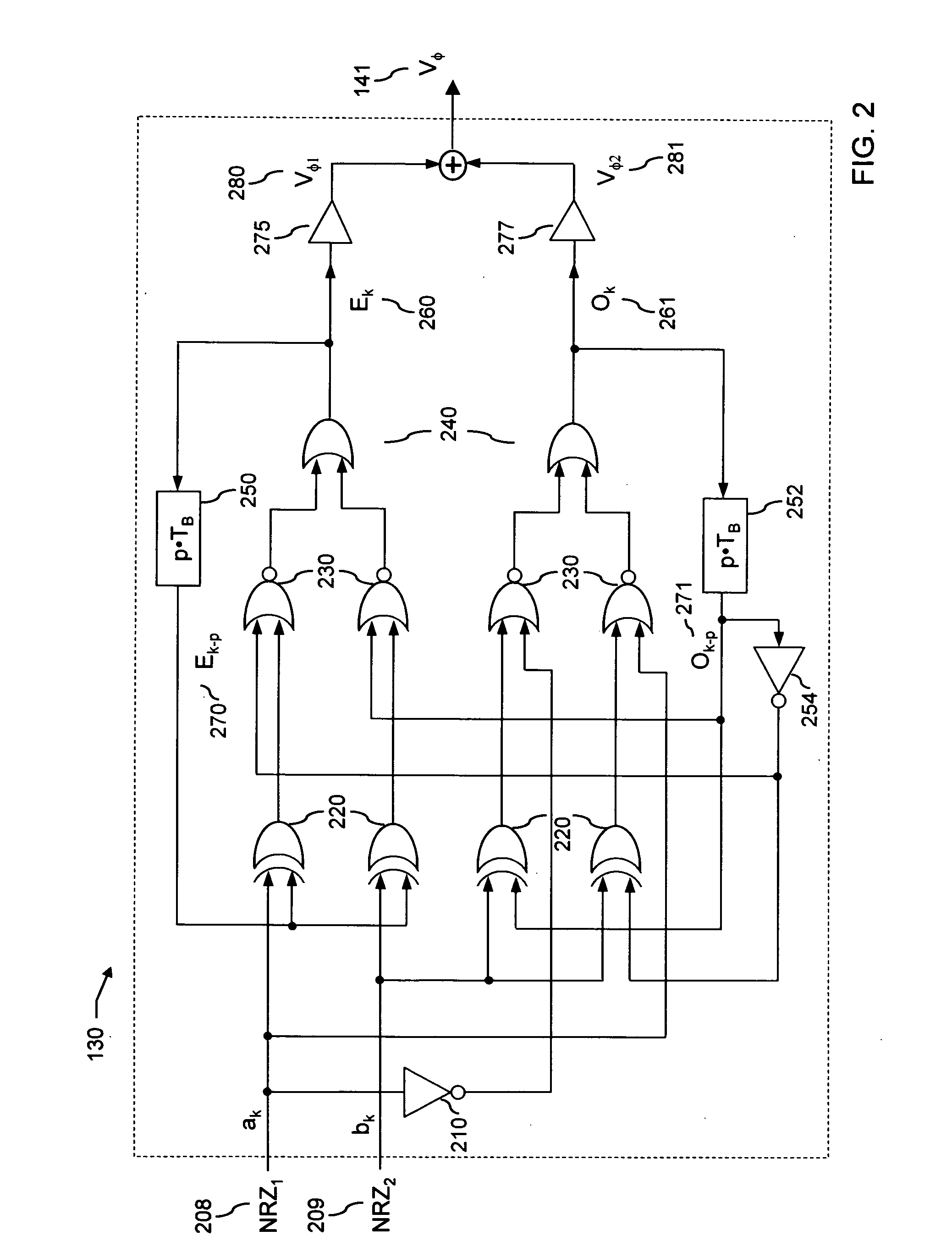
[0043]FIG. 2 includes a scheme of the said electrical pre-encoder circuit 130 for the said optical modulator 104, according to the said device 120 for modulating a RZ-DQPSK optical signal, to be used in the systems and modulators according to the second aspect of the present invention, the said pre-encoder including, among the other things: [0044] a) a first level of logical Exclusive-OR (XOR) gates 220 having at input the said first and second tributaries ak 208 and bk 209 and the encoded signals Ek-p 270 and Ok-p 271 delayed by p symbol periods TB. The said logical XOR gates can be realized, for instance, through an integrated GaAs module; [0045] b) a second level of logical NOR gates 230 having at input the said tributaries ak 208 and bk 209, the encoded signals Ek-p 270 and Ok-p 271 and the outputs of the first level gates; [0046] c) a third level of OR gates 240 having at input the signals generated by second level gates 230; [0047] d) two feedback circuits with delay lines p·T...

second embodiment

[0090] In the said method according to a fifth aspect of the present invention, a SM-RZ-DQPSK signal is generated, whereas the said number of input tributaries is n=2, and the optical phase assumes the four levels φj=φ0+(j−1)·2·π / 4, with j=1, 2, 3, 4, the electrical pre-encoding 130 operation being given by

Ek=((ak⊕Ek-p)+Ok-p′)′+((bk⊕Ek-p)+Ok-p)′

Ok=((bk⊕Ok-p)+ak′)′+((bk⊕Ok-p′)+ak)′,   (6)

with ak and bk the k-th bits of the input tributary sequences NRZ1 and NRZ2 respectively.

[0091] In a further embodiment of the said method according to a fifth aspect of the present invention, two SM-RZ-DQPSK optical signals are generated, the said first and second optical signals being polarization-time interleaved with orthogonal polarizations between them and delayed in time by approximately (h+½)TB, being h an integer number.

[0092] In all the aspects of the present invention, the optical connections among the said laser source and optical modulators are for instance implemented through the us...


PUM


Abstract

An apparatus and a method for transmitting at least a digital optical signal with return-to-zero phase-shift keying, employing a single optical modulator with dual-drive design, the said encoded optical signal having improved spectral efficiency and performances, and being generated by transmitters with simplified scheme; an optical communication system comprising the said apparatus, a transmission line and an apparatus to receive the said optical signal.

Description

FIELD OF THE INVENTION [0001] The invention relates to the transmission of optical signals in optical fiber communication systems, and more particularly to new devices and methods for modulating an optical carrier with improved performances and with a simplified scheme for the optical transmitter. BACKGROUND OF THE INVENTION [0002] Advanced optical modulation formats are commonly referred to signals alternative to the common Non-Return-to-Zero (NRZ) and Return-to-Zero (RZ), offering improved performances and tolerances to optical linear and nonlinear physical effects. The binary NRZ format consists in transmitting a first of the two logical states (for example the 1) through a substantially constant optical signal over the whole bit time slot TB, and the second of the two logical states (for example the 0) through a reduced or absent optical power over the whole bit slot. In the common RZ modulation format, one of the two logical states corresponds to the presence of an optical puls...

Claims


Application Information

Patent Timeline
Patent Type & Authority Applications(United States)
IPC IPC(8): H04B10/04H04B10/12
CPCH04B10/505H04B10/508H04B10/5055H04B10/5053
Inventor ZITELLI, MARIO
Owner ZITELLI MARIO
Why Eureka
Try Eureka