Sensing contact probe

Inactive Publication Date: 2007-01-18
SEAGATE TECH LLC
View PDF23 Cites 10 Cited by
  • Summary
  • Abstract
  • Description
  • Claims
  • Application Information

AI Technical Summary

Benefits of technology

[0007] In another embodiment, the probe tip face is a first one of a row of multiple probe tip faces suspended from a probe support that is common to the row of p

Problems solved by technology

One problem with microcantilevers is that the position and angle of the end of the beam tends to be somewhat variable, and this variability is thought to be due to variatio

Method used


Image

  • Sensing contact probe
  • Sensing contact probe
  • Sensing contact probe

Examples


Example

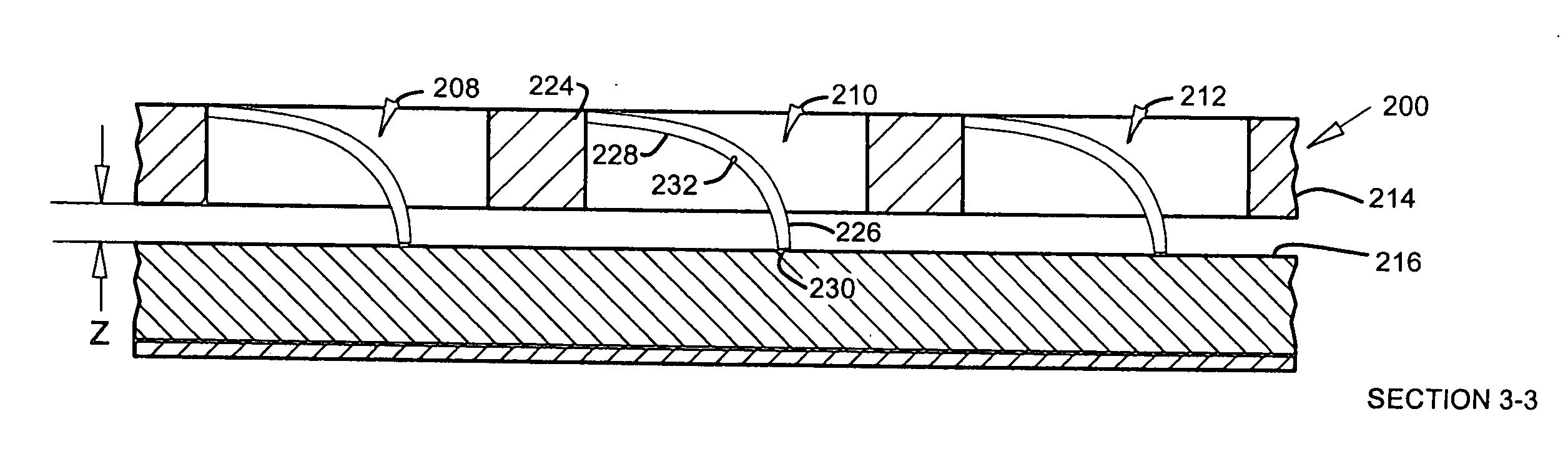
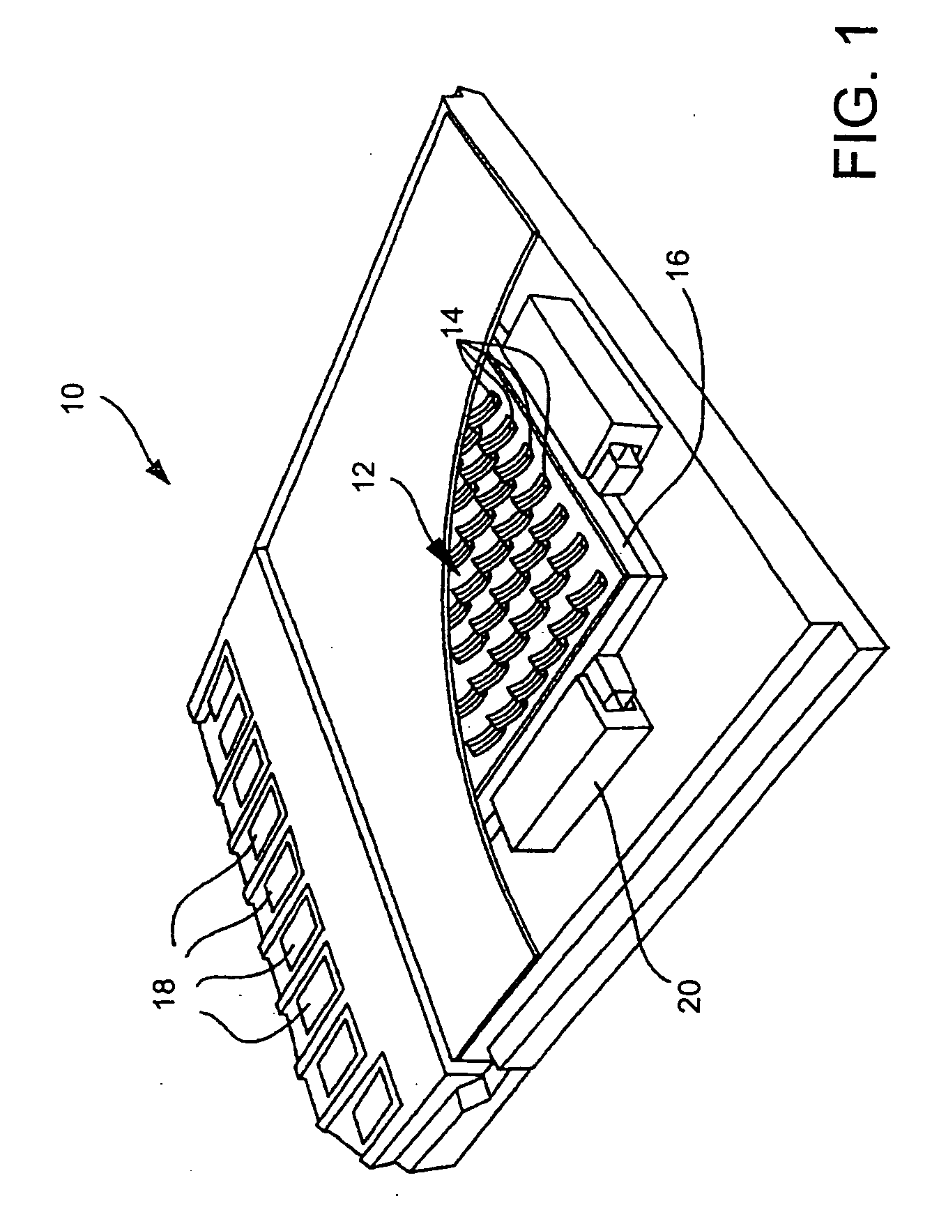
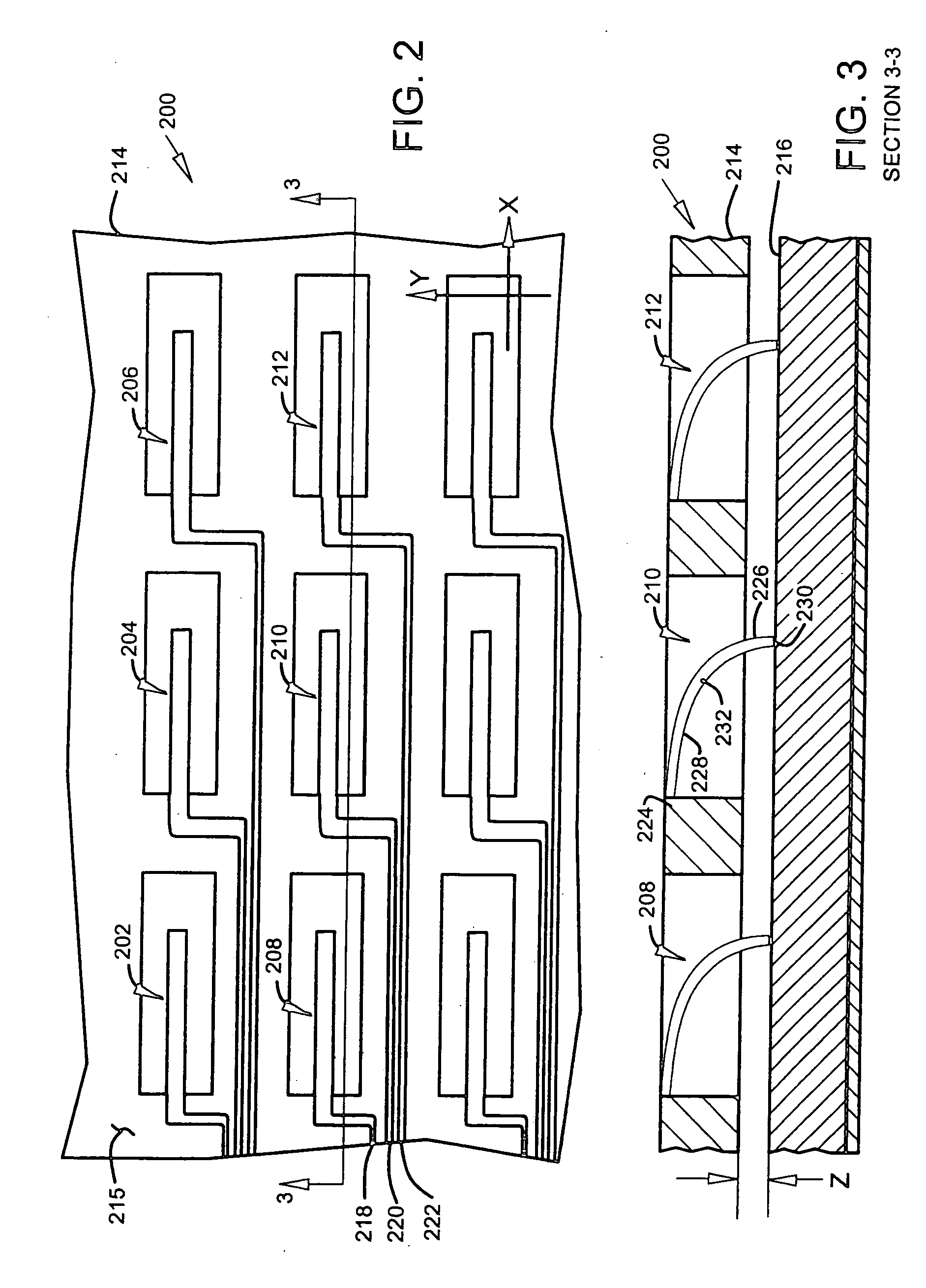
[0014] In the embodiments described below in connection with FIGS. 1-10, a sensing contact probe includes a beam body (microcantilever) that is formed of two layers that have differing residual stresses. The two layers are bonded together, and the differing amounts of residual stress bend the beam into an arc. The bent beam body serves as a spring that provides a preload force to keep a probe tip face at one end of the beam in contact with a surface that is to be scanned by the probe tip face. The sensing contact probes can be formed in arrays to provide simultaneous (parallel) scanning of multiple points on a surface. When individual beams in the array are misaligned due to manufacturing process variations, they are brought into alignment by adjusting a stress property of a stress relief region in the beam body. Lasers or chemical etching can be used to adjust the stress property. An array of beams can be brought into alignment with one another to ensure accurate placement and unif...


PUM


Abstract

A sensing contact probe includes a beam support and a probe. The probe has a bent beam body that extends from the beam support to a probe tip face that has a position and faces in an angular direction. The bent beam body has first and second beam layers bonded together and have differing residual stresses that bend the beam body. A stress relief region is formed in the bent beam body. The stress relief region has an adjusted stress property that adjusts the bending to control the probe tip face position and angular direction.

Description

FIELD OF THE INVENTION [0001] The present invention relates generally to contact probes, and more particularly but not by limitation to contact probes for use with ferroelectric memory. BACKGROUND OF THE INVENTION [0002] Microcantilevers are used as contact or support fingers in micromechanical devices. Microcantilevers typically have dimensions in the range of 1 to 100 micrometers and are formed by MEMS (microelectromechanical system) or MST (microsystem technology) methods. One problem with microcantilevers is that the position and angle of the end of the beam tends to be somewhat variable, and this variability is thought to be due to variations in processing conditions during fabrication which are difficult to control. The variability limits the precision with which devices which use microcantilevers can be made. A method and apparatus are needed to reduce variability in the position and angle of ends of microcantilever beams. [0003] Embodiments of the present invention provide s...

Claims


Application Information

Patent Timeline
IPC IPC(8): G01B5/00
CPCB82Y10/00G11B9/1436G11B9/02
Inventor GAGE, EDWARD CHARLESHSIA, YIAO-TEEPENG, WEIKIELY, JAMES D.
Owner SEAGATE TECH LLC
Why Eureka
Try Eureka