Space frames and connection node arrangement for them

a technology of space frames and connection nodes, applied in the direction of girders, heat collector mounting/supports, lighting and heating apparatus, etc., can solve the problems of node moment load or other undesired load applied, affecting the magnitude of actual load in the framing member as compared to the design load magnitude, and the cost and difficulty of assembling such grids

Active Publication Date: 2007-01-18
GOSSAMER SPACE FRAMES
View PDF17 Cites 83 Cited by
  • Summary
  • Abstract
  • Description
  • Claims
  • Application Information

AI Technical Summary

Benefits of technology

[0105]5] Many benefits and advantages are afforded by this invention and its aspects and features described above. The node connectors enable certain chords of a DLG space frame to extend continuously though them. The node connectors can be used with space frame framing members of substantially any cross-sectional configuration desired; they are not limited to use with members having round or rectangular cross-sections. Node connectors and framing members can be extruded for low cost and dimensional precision. Node connectors and framing members can be made of materials having uniform metallurgical properties so that, among other benefits, space frames incorporating them are little affected dimensionally by temperature changes. The node connectors enable framing members of differing numbers, size and cross-sectional configuration to be effectively interconnected at a given node in a space frame. The node connectors can be defined to enable good, even ideal, positioning and alignment of framing members at a space frame node so that there are minimal or no eccentricities of framing member axes relative to each other at a node. The node connectors enable convenient use of variable bay spacing in a space frame, enabling the overall frame to efficiently carry design loads. The node connectors can be defined to provide interconnections between framing members in a diverse range of positions and numbers, thus enabling the use of DLG design and construction principles in more complex structures including non-static (movable) structures for electromagnetic radiation focusing applications such as movable mirror or reflector support armatures in solar power generation facilities and in radio and optical telescopes. Use-specific elements can be accommodated in space frames, such as mountings for solar reflectors, torque members, and other supports and accessories.

Problems solved by technology

The reason for the use of pinned connections in DLGs is the cost and difficulty of assembling such grids having moment connections of the framing members at or to the nodes.
Eccentricity at a DLG node causes the node to have moment loads or other undesired loads applied to it.
Clearances at pinned connections in a DLG also can cause the grid framing members to have effective lengths between nodes which deviate from design lengths, thereby affecting the magnitudes of the actual loads in the framing members as compared to design load magnitudes.
It is apparent, therefore, that existing structures and techniques for establishing connections of framing members to nodes in DLGs have deficiencies which adversely affect the load carrying capacities of an overall DLG and of the framing members present in it.
The principal factors effecting the cost of a given DLG are primarily the cost of the materials used to define the grid components and secondarily the cost of labor to assemble those components.

Method used


Image

  • Space frames and connection node arrangement for them
  • Space frames and connection node arrangement for them
  • Space frames and connection node arrangement for them

Examples


Embodiment Construction

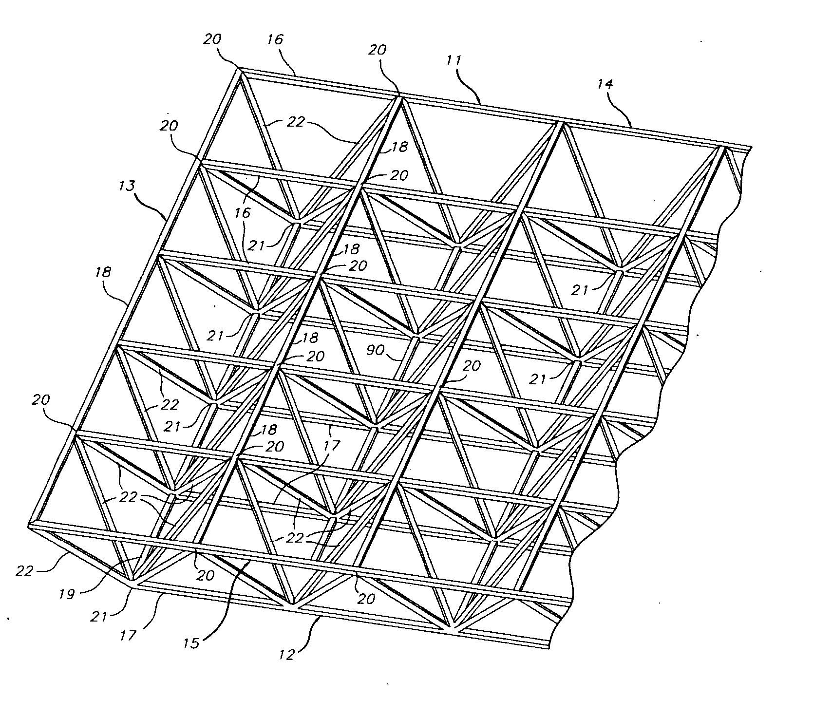
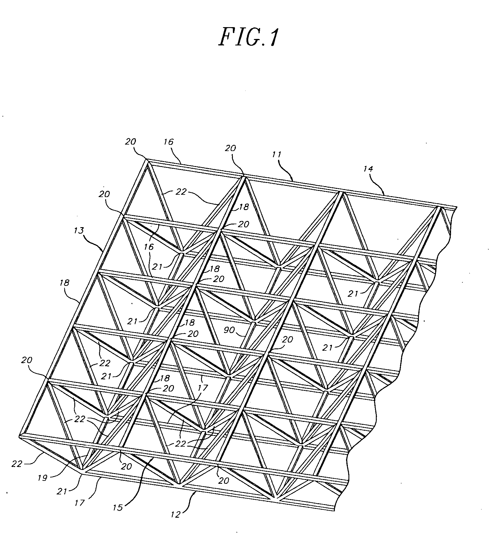
[0049]FIG. 1 is a perspective view of a portion of a rectilinearly subdivided DLG space frame 10. Frame 10 is composed of framing members which are disposed to define top 11 and bottom 12 layers of the frame and to interconnect those layers in an arrangement which causes frame layers 11 and 12 to be in spaced parallel relation to each other. Layers 11 and 12 can also be called grids, hence the name double layer grid (DLG) for the type of space frame shown in FIG. 1.

[0050] The framing members of DLG 10 are comprised by chords which are interconnected to define top and bottom layers 11 and 12 of the DLG which has an end 13 and opposite sides 14 and 15. The chords which extend along the length of the DLG can be and preferably are continuous (subject to limitations on the lengths available) and, for present purposes, are called major chords. Thus, DLG 10 includes upper major chords 16 and lower major chords 17. In each layer of DLG 10, the upper and lower major chords are interconnecte...


PUM


Abstract

A node connector in a double layer grid-type of space frame preferably is an extrusion which includes an open-ended tubular portion for snugly at least substantially encircling a frame chord member of desired cross-sectional configuration which is disposable in the passage. The node connector has fixed external elements which extend along the connector parallel to the passage. Those elements define facing parallel flat surfaces arranged in at least two pairs of such surfaces. The surfaces of each pair lie equidistantly from a center plane between them. Each center plane is parallel to the passage axis and preferably includes the passage axis. Each pair of facing flat surfaces of the node connector can cooperate closely with opposite flat surfaces at the end of each of other frames framing member placed between the facing surfaces. The node connector can be secured to a chord member in its passage and to ends of other framing members by shear pins which have zero clearances in node connector holes and in holes or passages through the respective framing members. The space frame can be a movable armature for a curved solar reflector, the space frame having a V-shaped major surface. At least some of the framing members can be thin wall tubes modified to have opposing, flat-exterior wall zones along the length of each tube and in which the wall thickness is locally increased and through which shear pin holes are defined.

Description

CROSS-REFERENCE TO RELATED APPLICATION [0001] This application is a continuation-in-part under 35 U.S.C. § 120 of co-pending application Ser. No. 10 / 932,173 filed Aug. 31, 2004.FIELD OF INVENTION [0002] This invention pertains to structural space frames. More particularly, it pertains to other-than-shell space frames and to connection node arrangements and other structural elements for such frames. BACKGROUND OF THE INVENTION [0003] A space frame is a network of structural framing members, such as tubes, interconnected at multi-member connection points (commonly called “nodes”) in such a way that the whole structure behaves as one structural element. By contrast, in the typical framing of beams and columns, as in buildings, structural elements often act independently of each other and can have completely separate force paths. [0004] Two broad classes of space frames are recognized in the art. They are single layer grids and double (multiple) layer grids (DLGs). A single layer grid i...

Claims


Application Information

Patent Timeline
Patent Type & Authority Applications(United States)
IPC IPC(8): E04C3/02
CPCE04B1/19E04B1/1903E04B2001/1933E04B2001/1936E04B2001/1975E04B2001/1984E04H12/00E04C2003/0495F24J2/52F24J2/5233H01Q15/18Y02E10/47E04B2001/199F24S25/00F24S25/13
Inventor REYNOLDS, GLENN A.HACKBARTH, DEAN R.CURTIS, GARY N.
Owner GOSSAMER SPACE FRAMES
Why Eureka
Try Eureka