Turbomachine with angular air delivery

Active Publication Date: 2007-01-18
SN DETUDE & DE CONSTR DE MOTEURS DAVIATION S N E C M A
View PDF1 Cites 28 Cited by
  • Summary
  • Abstract
  • Description
  • Claims
  • Application Information

AI Technical Summary

Benefits of technology

[0006] A main object of the present invention is thus to mitigate such drawbacks by proposing a turbomachine in

Problems solved by technology

These successive modifications to the angle of air flow through the turbomachine require intense aerodynamic forces to be produced by the stator in the compr

Method used


Image

  • Turbomachine with angular air delivery
  • Turbomachine with angular air delivery
  • Turbomachine with angular air delivery

Examples


Embodiment Construction

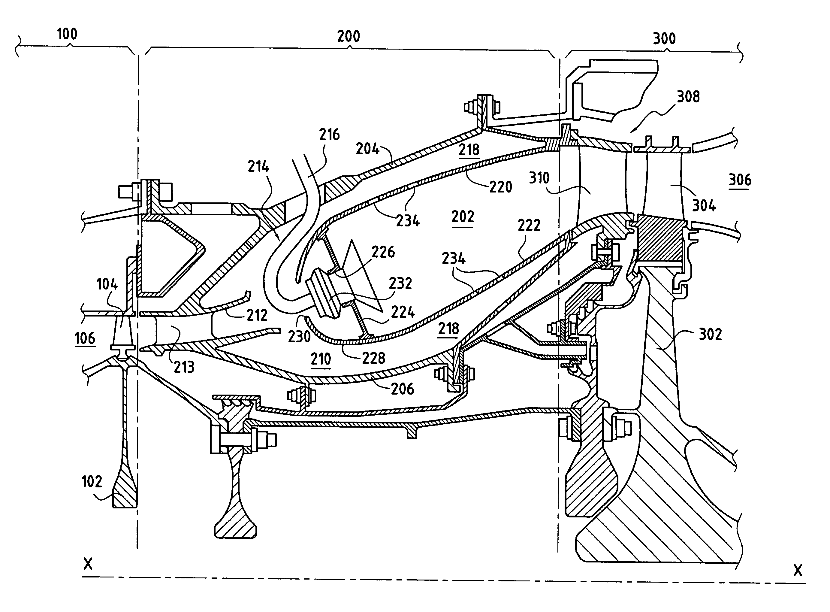
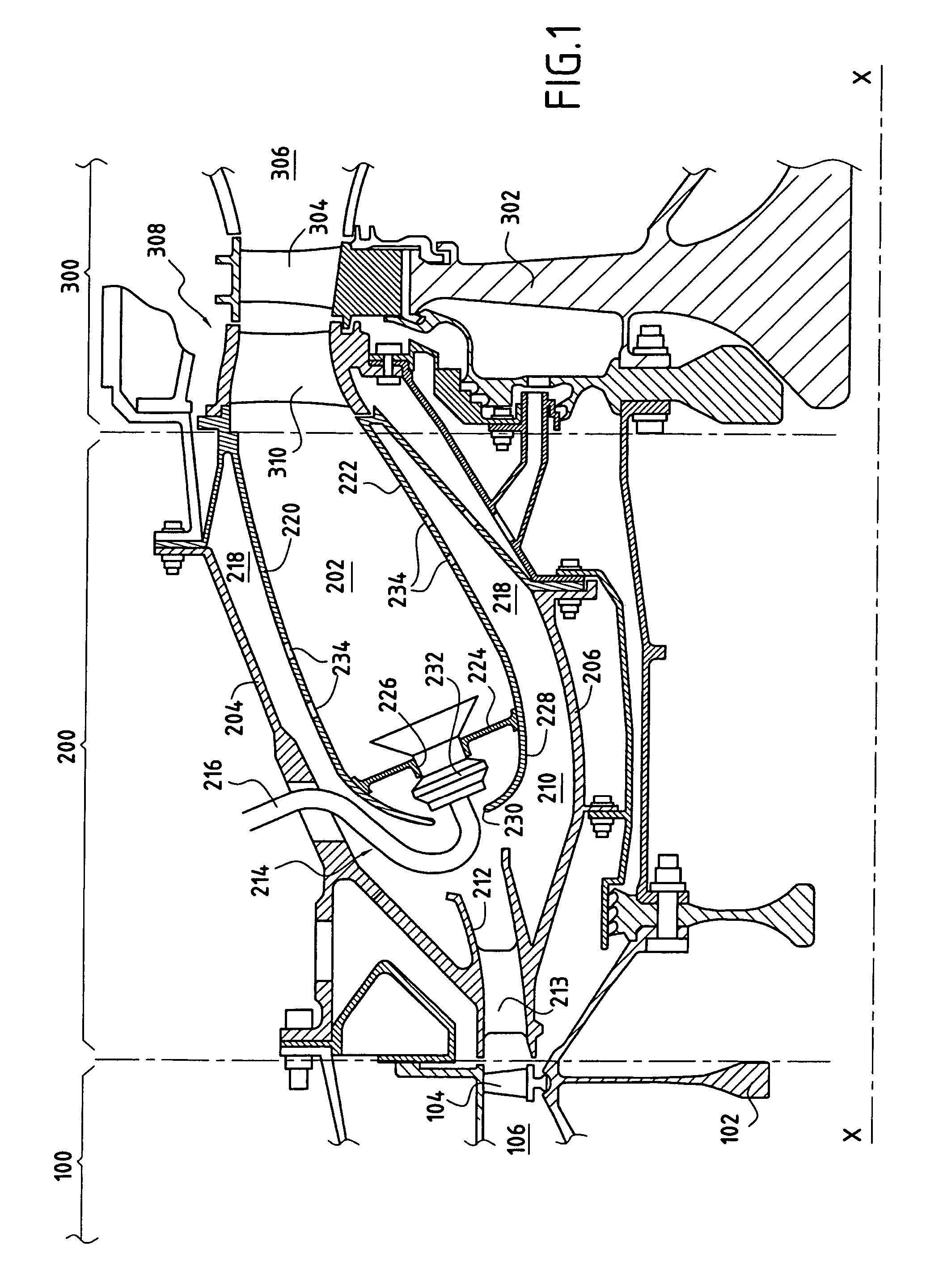
[0023] The turbomachine shown in part in FIG. 1 has a longitudinal axis X-X. Along this axis it comprises in particular an annular compression section 100, an annular combustion section 200 located at the outlet from the compression section 100 in the flow direction of air passing through the turbomachine, and an annular turbine section 300 disposed at the outlet from the combustion section 200. The air injected into the turbomachine thus passes in succession through the compression section 100, then the combustion section 200, and finally the turbine section 300.

[0024] The compression section 100 is in the form of a plurality of stages of moving wheels 102 each carrying blades 104 (only the last stage of the compression section is shown in FIG. 1). The blades 104 of these stages are disposed in an annular channel 106 through which the turbomachine air passes and of section that tapers from upstream to downstream. Thus, as the air injected into the turbomachine passes through the c...


PUM


Abstract

A turbomachine assembly comprising: an annular compression section; a casing formed by an outer annular shell (204) and an inner annular shell (206) secured inside the outer shell by means of a plurality of radial support arms (208); an annular combustion section housed inside the casing; and an annular turbine section. The air coming from the compression section presents rotary motion with an angle of inclination relative to a longitudinal axis (X-X) of the turbomachine, and the combustion section includes angular distribution means for determining air flow direction so as to impart on the gas leaving the combustion section rotary motion with an angle of inclination that is equal to or greater than the angle of inclination of the air leaving the compression section, said angular distribution means being formed by the support arms (208), each of which presents an angle of inclination relative to the longitudinal axis (X-X) of the turbomachine that is greater than or equal to the angle of inclination of the air leaving the compression section.

Description

BACKGROUND OF THE INVENTION [0001] The present invention relates to the general field of determining the flow direction of the air that passes through a turbomachine for aviation or terrestrial use. [0002] A turbomachine is typically made up of an assembly comprising in particular an annular compression section for compressing the air that passes through the turbomachine, an annular combustion section disposed at the outlet from the compression section and within which the air coming from the compression section is mixed with fuel so as to be burnt therein, and an annular turbine section disposed at the outlet from the combustion section and having a rotor that is driven in rotation by the gas coming from the combustion section. [0003] The compression section is in the form of a plurality of stages of moving wheels each carrying blades that are disposed in an annular channel through which the turbomachine air passes, and of section that tapers from upstream to downstream. The combus...

Claims


Application Information

Patent Timeline
IPC IPC(8): F23R3/42
CPCF23C5/32F23R2900/03042F23R3/50F23R3/12
Inventor BURET, MICHEL ROGERCAZALENS, MICHEL PIERREHERNANDEZ, DIDIER HIPPOLYTE
Owner SN DETUDE & DE CONSTR DE MOTEURS DAVIATION S N E C M A
Why Eureka
Try Eureka