Check patentability & draft patents in minutes with Patsnap Eureka AI!

Snapping mechanism of telescoping tent pole

Inactive Publication Date: 2007-01-18
CHOI KWAN JUN
View PDF8 Cites 73 Cited by
  • Summary
  • Abstract
  • Description
  • Claims
  • Application Information

AI Technical Summary

Benefits of technology

[0006] It is therefore a main object of the present invention to provide a snapping mechanism of telescoping tent pole, which has a smaller volume and lower production cost than the same, meanwhile guarantee to meet the necessary of carrying out the dilatation operation of huge tent pole smoothly.
[0009] Utilizing the same, because the V-shaped elastic latch is directly set upon in the inside of the inner tube of the tent pole, cooperating to the clip ring integrated with the button set upon the outside, as tending to pitch up each tent pole just like drawing out the inner tube from the external tube, due to the V-shaped elastic latch located at the inside of the inner tube, and the latch bolt fit into the location hole of the inner tube, when the moving location hole of the inner tube is exactly faced to the location hole of the external tube, under the restoring force of the V-shaped elastic latch, the latch bolt slips into the location hole of the external tube to lock them together; and as tending to fold up the tent pole, just need to press down the button hinged on the clip ring to push the latch bolt back to the inside pressing down the V-spring to release the external tube from the lock state, the inner tube can be pushed back by sliding; so, the clip ring of the snapping mechanism of the telescoping tent pole provided by the present invention saves the space containing the conventional spring, the volume of the clip ring can be designed to smaller, better in looking than the prior art, and the production cost is also lower, and leaves a certain space in use.

Problems solved by technology

After studying the same, we are not difficult to find that the location pin and the restoring spring are all assembled into the clip ring 1′, so the whole body of the clip ring 1′ has to offer a certain space for containing them, so that the external volume of the snapping mechanism is became quite big, and the production cost is gone up, and affect to the outline of the pitch-up tent, and occupy a certain space as fold-up.

Method used


Image

  • Snapping mechanism of telescoping tent pole
  • Snapping mechanism of telescoping tent pole
  • Snapping mechanism of telescoping tent pole

Examples


Embodiment Construction

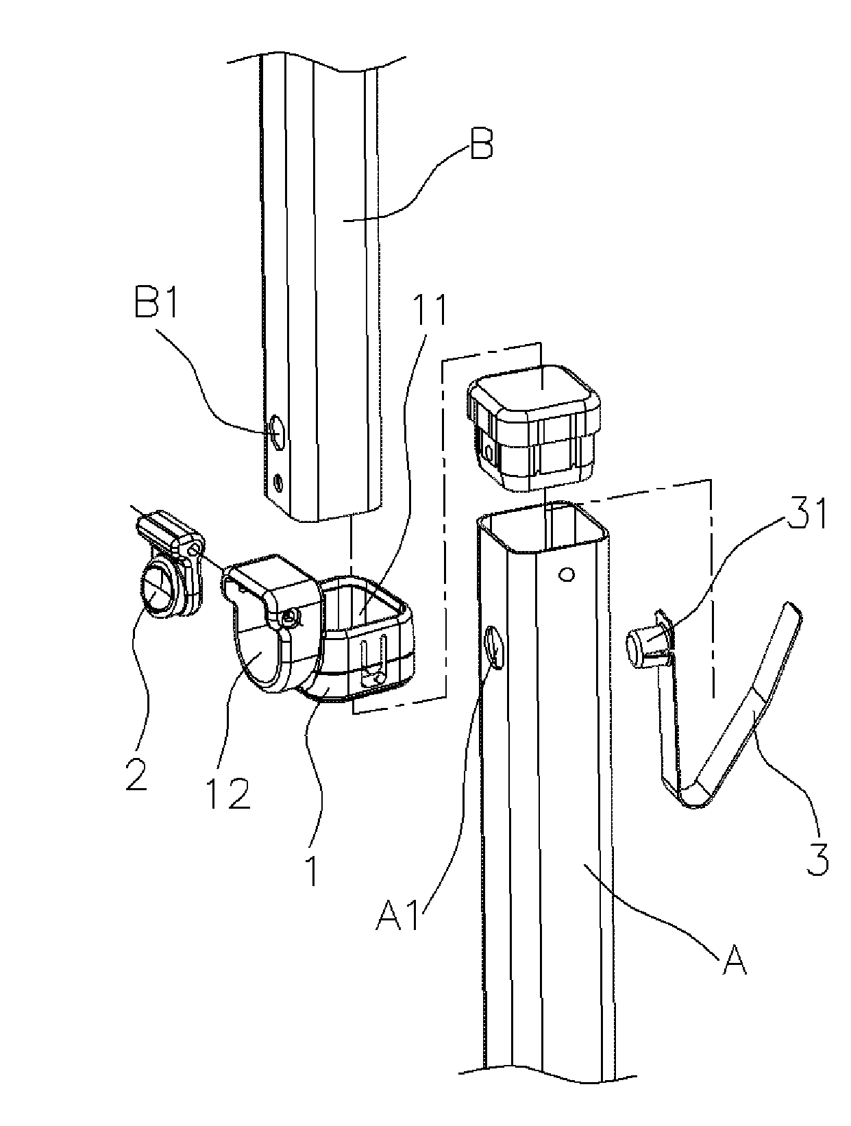
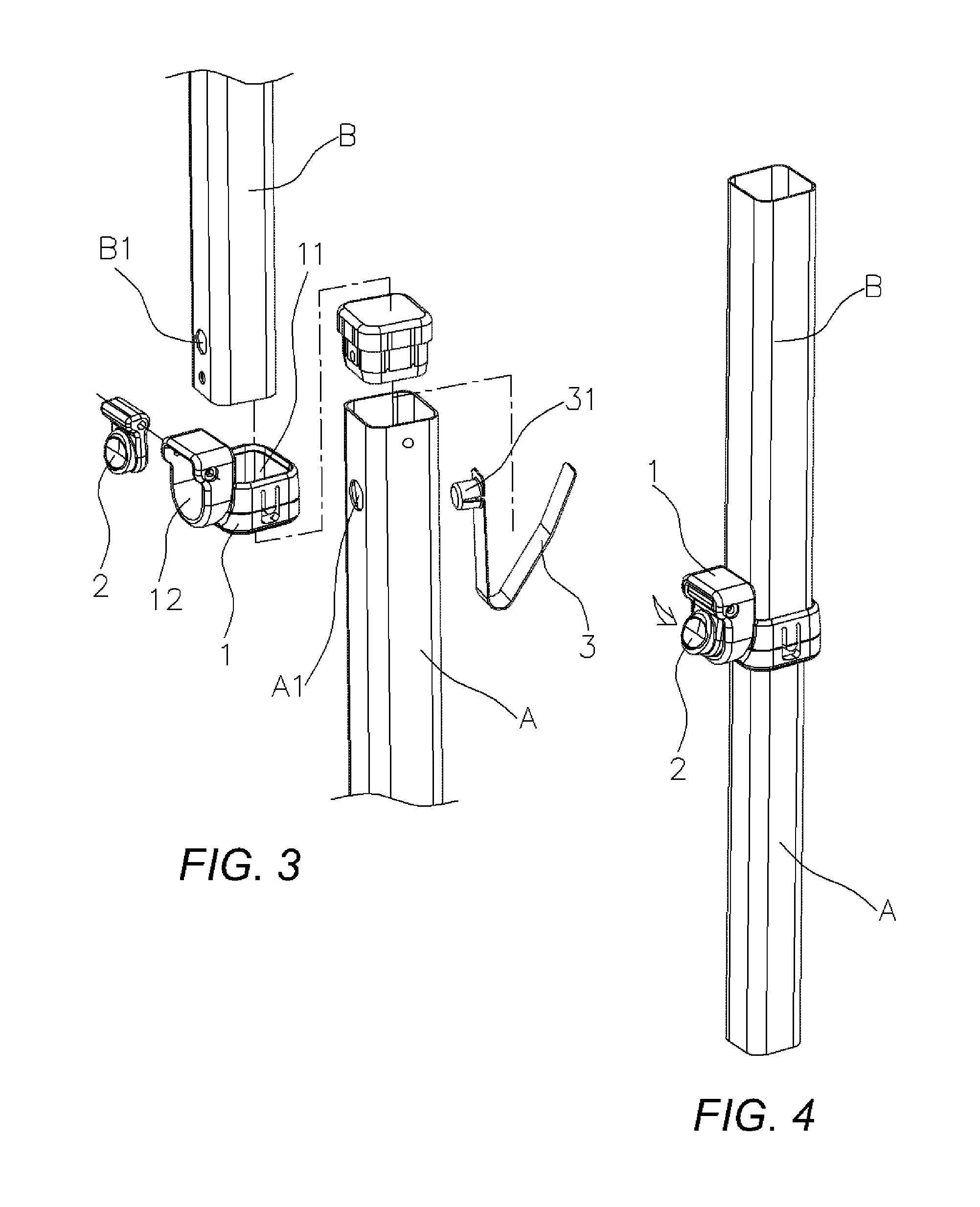
[0014] Referring to FIG. 3 and FIG. 4, the snapping mechanism provided by the present invention is typically comprised of a clip ring 1, a button 2 and an elastic latch 3;

[0015] Said clip ring 1 has a clamp sleeve 11 formed on one side axially for fastening on the end of external tube B of the tent pole, and a housing 12 formed on another side in radial.

[0016] Said button 2 is hinged on the inside of said housing 12 of the clip ring 1 with the upper or low portion, the free portion is exactly facing to a location hole B1 of the external tube B;

[0017] Said elastic latch 3 is a V-shaped elastic strip as a V-spring, extending a latch bolt 31 out from a free end outward, said elastic latch 3 is located at inside of the inner tube A by fitting the latch bolt 31 into the location hole A1 and another free end pressing against the back side wall of the hollow inside of the inner tube A.

[0018] As tending to pitch up the telescoping tent pole just like drawing out the inner tube A from th...


PUM


Abstract

The present invention provides a snapping mechanism of telescoping tent pole typically comprised of a clip ring, a button and an elastic latch; said clip ring has a clamp sleeve formed on one side axially for fastening on the end of external tube of the tent pole, and a housing formed on another side in radial, wherein said button is hinged on the inside of said housing with the upper or low portion, said V-shaped elastic latch is set upon the inside of the inner tube of the tent pole rightly so that a latch bolt extended out from one free end in radial catches into and stretches out via a location hole of the inner tube. Because the V-shaped elastic latch is directly set upon in the inside of the inner tube of the tent pole, just only cooperating to the clip ring integrated with the button set upon the outside can carry out locking and releasing the inner and external tubes function, therefore the clip ring of the snapping mechanism of the telescoping tent pole provided by the present invention saves the space containing the conventional spring, the volume of the clip ring can be designed to smaller, better in looking than the prior art, and the production cost is also lower, and leaves a certain space in use.

Description

BACKGROUND OF THE INVENTION [0001] 1. Field of the Invention [0002] The present invention relates to a snapping mechanism of telescoping tent pole used in big scale tent. [0003] 2. Description of Prior Art In accordance with the conventional large scale foldable tent, because pulling out or pushing back the each pole composed of inner and external telescopic tubes need to exerting bigger force, for facilitating to dilatation of each integrated pole, a snapping mechanism is built upon the expansion joint. [0004] A conventional snapping mechanism using in a huge tent pole is shown in FIG. 1 and FIG. 2, which is comprised of a clip ring 1′, a button 2′, a restoring spring 3′ and a location pin 4′; said clip ring 1′ has a clamp sleeve 11′ formed on one side axially for fastening on the end of external tube A, and a housing 12′ formed on another side in radial, said button 2′ is hinged on the middle point of the housing 12′ with the middle portion, said restoring spring 3′ is set up betw...

Claims


Application Information

Patent Timeline
IPC IPC(8): E04H15/60F16B7/10
CPCE04H15/60Y10T403/32467F16B7/105
Inventor CHOI, KWAN-JUN
Owner CHOI KWAN JUN
Features
  • R&D
  • Intellectual Property
  • Life Sciences
  • Materials
  • Tech Scout
  • Unparalleled Data Quality
  • Higher Quality Content
  • 60% Fewer Hallucinations
Learn More