Heat exchanger

a technology of heat exchanger and insert, which is applied in the direction of heat exchange apparatus safety devices, lighting and heating equipment, and stationary conduit assemblies, etc., can solve the problems of tube in the neighborhood of the root being broken, the difference in the amount of thermal expansion between the tubes and the insert is liable to generate thermal stress, and the effect of reducing the efficiency of heat exchang

Inactive Publication Date: 2007-01-18
DENSO CORP
View PDF1 Cites 21 Cited by
  • Summary
  • Abstract
  • Description
  • Claims
  • Application Information

AI Technical Summary

Benefits of technology

[0017] In view of this fact, the object of the present invention is to provide a heat exchanger in which the thermal distortion is reduced while, at the same time, the pressure resistance performance is secured.
[0047] By forming at least a notch (76) in the base portion (71) and the rib-side expansions (77) on a pair of the ribs (72) in this way, the stress generated along the length of each insert can be positively absorbed.

Problems solved by technology

The difference in the amount of thermal expansion between the tubes and the insert is liable to generate thermal stress due to thermal distortion at the root (coupling) between as the core plate and the tubes adjacent to the insert.
A repeated change in temperature and hence a repeated chance in thermal stress poses the problem that the tubes in the neighborhood of the root may be broken.

Method used


Image

  • Heat exchanger
  • Heat exchanger
  • Heat exchanger

Examples


first embodiment

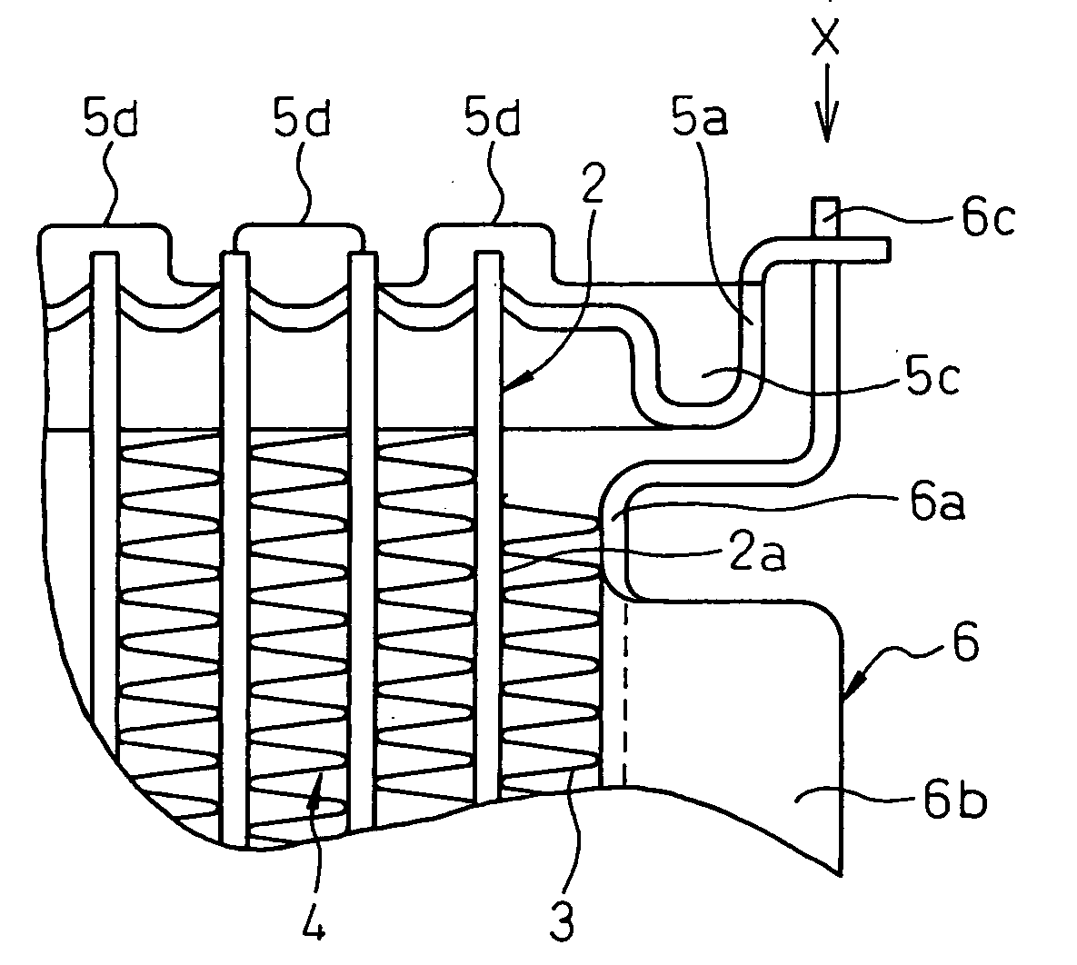
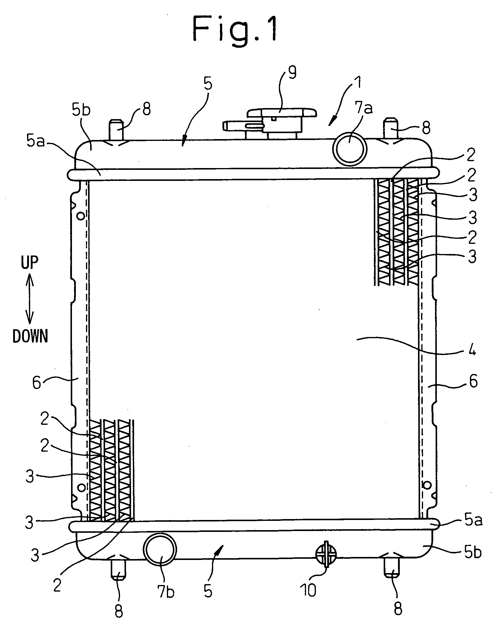
[0089] A header tank 5 extends in the direction horizontal direction in this embodiment) perpendicular to the length of the tubes 2 at each longitudinal end (upper and lower ends in this embodiment) of the tubes 2 and communicates with the plurality of the tubes 2. Each header tank 5 includes a core plate 5a with the tubes 2 coupled by insertion thereinto and a tank body 5b providing the internal space of the tank with the core plate 5a. the core plate 5a is formed of a metal (such as an aluminum alloy) and the tank body 5b is formed of resin.

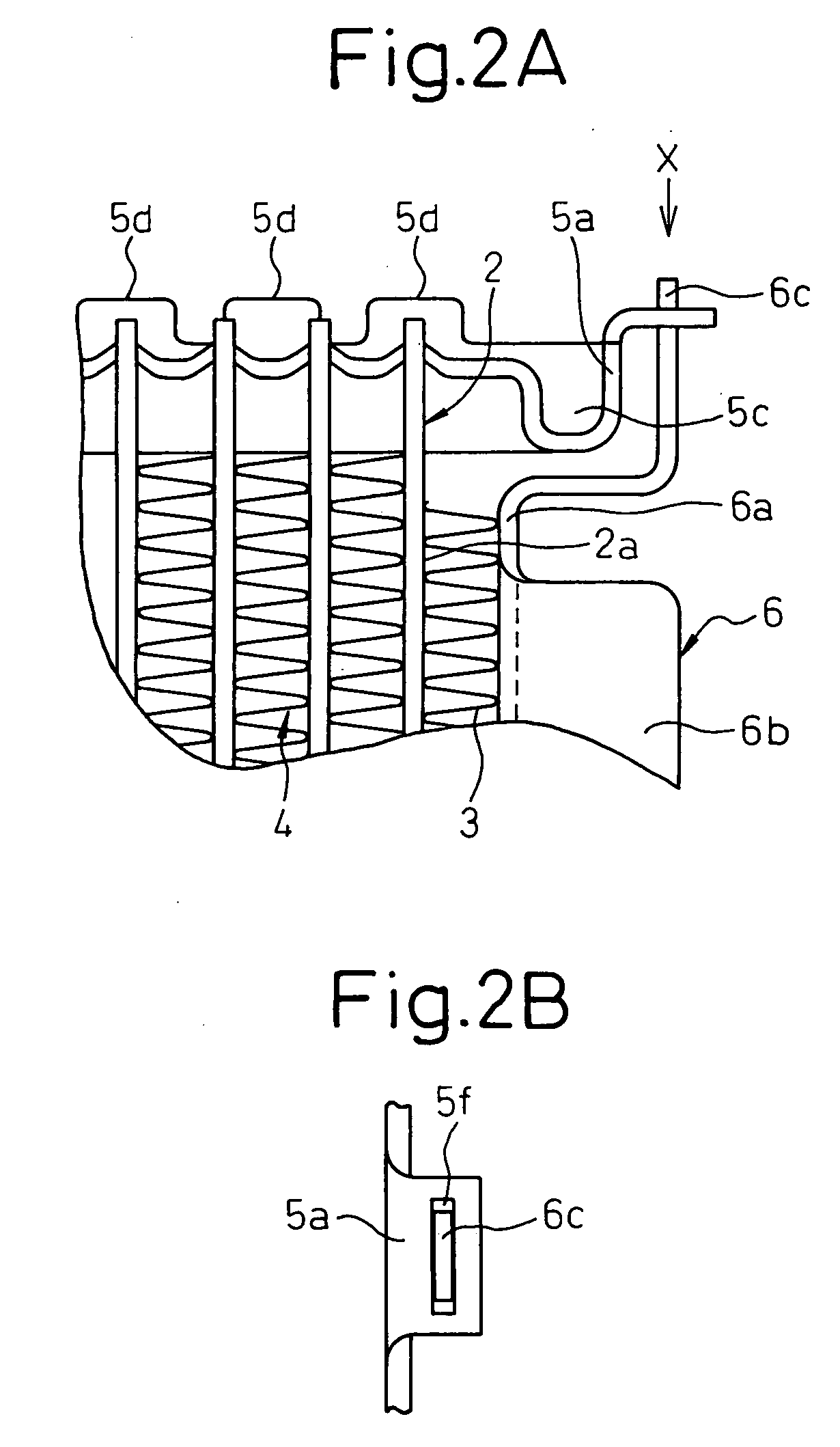
[0090] As shown in FIG. 2A, packing (not shown), made of an elastic material such as rubber, is arranged in a groove 5c formed along the whole peripheral edge of the core plate 5a thereby to close the gap between the tank body 5b and the core plate 5a in liquid tight fashion. A plurality of hooks 5d are erected on the peripheral edge of the core plate 5a. By fixedly caulking the hooks 5d on the flange formed on the outer peripheral edge of the...

fifth embodiment

[0114]FIG. 6A is an enlarged view of the essential parts of the radiator 1 and FIG. 6B an enlarged plan view of the fitting between the tank body 5b and the insert 6 taken from the X direction in FIG. 6A. As shown in FIG. 6A, each longitudinal end of the tank body 5b is formed with a protrusion 12 outside of the tank body 5b. The protrusion 12 is formed of resin and is molded integrally with the tank 5b.

[0115] The protrusion 12 is formed with a through hole 12a. The through hole 12a is configured to be fitted on the core plate 5a with the insert end portion 6a inserted in the through hole 5f.

[0116] As described above, by fitting the insert end portion 6c in the protrusion 12 of the tank body 5b of resin, the fitting between the insert 6 and the tank body 5b is prevented from being brazed and, therefore, effects similar to the first embodiment are achieved.

[0117] Next, a sixth embodiment of the invention will be explained with reference to FIGS. 6A, 6B. The sixth embodiment is di...

sixth embodiment

[0118] the tank body 5b and the protrusion 12 are formed of a metal (such as aluminum alloy), and the protrusion 12 is formed integrally with the tank body 5b. Also, the brazing material on the fitting between the tank body 5b and the insert 6, i.e. the inner wall portion of the through hole 12a and the portion of the insert end portion 6c corresponding to the through hole 12a is cut off.

[0119] As described above, the insert 6 is fitted in the protrusion 12 of the tank body 5b and the brazing material on the fitting between the tank body 5b and the insert 6 is cut off thereby to prevent the brazing. Thus, effects similar to those or the first embodiment are achieved.

[0120] Next, a seventh embodiment of the invention is explained with reference to FIGS. 7, 8. The seventh embodiment is different from the first embodiment in that both the fins 3 and the inserts 6 are formed of a bare material. In FIGS. 7, 8, component parts similar or identical to those of the first embodiment are de...


PUM


Abstract

A heat exchanger comprises a core portion including a plurality of tubes with a heat medium flowing therein and fins coupled to the outer surface of the tubes for promoting heat exchange with the heat medium, a pair of header tanks extending in a direction perpendicular to the length or the tubes at the longitudinal ends of the tubes and communicating with the tubes, and a pair of inserts arranged substantially parallel to the length of the tubes at the ends of the core portion to receive the heat transmitted from the core portion and having the ends thereof supported on the header tanks, each header tank includes a core plate with the tubes fixed thereon and a tank body providing the internal space of the tank with the core plate, and the ends of each insert are arranged outside the internal space of the tank and the insert is movably fitted in the header tank and along the length thereof and is immovable in a direction perpendicular to the length thereof.

Description

BACKGROUND OF THE INVENTION [0001] 1. Field of the Invention [0002] This invention relates to a heat exchanger or, in particular, to a heat exchanger effectively applicable to a multiflow radiator for cooling the cooling water of the internal combustion engine of an automotive vehicle. [0003] 2. Description of the Related Art [0004] A conventional multiflow radiator, as shown in FIG. 9, includes a core portion J4 having a plurality of tubes J2 and fins J3 coupled to the outer surface of the tubes J2, a header tank J5 communicating with the plurality of the tubes J2 and an insert J6 arranged at the end of the core portion J4 for reinforcing the core portion J4. [0005] The header tank J5 is configured of a core plate J5a coupled with the tubes J2 and a tank body J5b providing the internal space of the tank. The tubes J2 and the insert J6 are coupled to the core plate J5a by brazing after being inserted into the header tank J5. [0006] In this radiator, if the temperature of the cooling...

Claims


Application Information

Patent Timeline
Patent Type & Authority Applications(United States)
IPC IPC(8): F28D1/00
CPCF28D1/05366F28F2265/26F28F9/0217
Inventor KAMIYA, YOSHIHIKONINAGAWA, TOSHIHIDEHIROSE, HIROKAZUOSAKABE, HIROYUKISUGITO, HAJIME
Owner DENSO CORP
Why Eureka
Try Eureka