Turbo-machine impeller manufacturing

a technology of turbo-machine and impeller, which is applied in the direction of machines/engines, liquid fuel engines, turbines, etc., can solve the problems of affecting or even hindering the manufacturing of metallic components, deformation of individual layers, and little or no application of additive manufacturing processes for manufacturing massive metallic components. , to achieve the effect of reducing the weight of the turbo-machine impeller

Active Publication Date: 2018-02-27
NUOVO PIGNONE TECH SRL
View PDF38 Cites 15 Cited by
  • Summary
  • Abstract
  • Description
  • Claims
  • Application Information

AI Technical Summary

Benefits of technology

[0009]A reduction of the weight of a turbo-machine impeller manufactured by an additive-manufacturing-type production process is achieved by controlling the high energy source used for melting or sintering the powder material such that the bulk portions of the turbo-machine impeller are formed with an interior lattice structure, surrounded by a solid structure, i.e. by a sort of a skin which provides for a solid, continuous outer surface. Lattice structures can be obtained by suitably controlling the energy delivered by the high energy source, such that the powder material is melted spot-wise, and individual volumes of melted powder material will solidify and adhere one to the other leaving volumes there between, where the powder material is not melted and will subsequently be removed leaving an empty space within the solidified material forming the lattice structure.
[0017]By solidifying the powder material to form a lattice structure, rather than a solid structure, in the bulky portion of the impeller, improves heat dissipation and prevents or reduces thermal stresses and deformations, thus making additive-manufacturing of massive impellers feasible. Less thermal energy is required to generate a lattice versus a solid structure. Thus, the total amount of heat that has to be dissipated is reduced. Additionally, free space remains in the non-melted portions of the layer, where heat dissipation is made easier and faster. Both factors contribute to the reduction of thermal deformations.
[0019]According to some embodiments, the layers of powder material are deposited in a heated confinement structure. The temperature of the impeller can thus be controlled. Residual stresses in the final product can be prevented or reduced by controlling the temperature vs. time curve, e.g. as a function of the material used, the shape of the product, the kind of high energy source used, or other process parameters.
[0021]The lattice structure is sufficiently strong to resist mechanical and thermal stresses, but has a specific weight lower than the solid material forming the remaining portions of the impeller, thus reducing the overall impeller weight. The un-solidified powder material remaining in the lattice structure can be removed, e.g., by blowing or sucking. To facilitate removal of the residual un-solidified powder material, one or more apertures can be provided in the solid skin structure surrounding the lattice structure. The apertures can be generated during the layer by layer manufacturing process. In other embodiments, the apertures can be machined in the finished impeller.

Problems solved by technology

Additive-manufacturing processes have little or no applications for manufacturing massive metallic components.
Thermal stresses generated in the bulky structure of massive components causes deformations of the individual layers formed during the manufacturing process.
In the case of large massive components, the deformation caused by thermal stress during melting and subsequent solidification of one layer of powder material can be so extensive as to negatively affect or even hindering the deposition of the subsequent powder layer, as the lower solidified and deformed layer obstructs the movement of the rack used to distribute the subsequent powder layer.
Turbo-machine impellers are subject to high dynamic mechanical stresses and are sometimes required to work in a particularly difficult environment, for example when acid gas or wet gas is processed by the compressors.

Method used


Image

  • Turbo-machine impeller manufacturing
  • Turbo-machine impeller manufacturing
  • Turbo-machine impeller manufacturing

Examples


Embodiment Construction

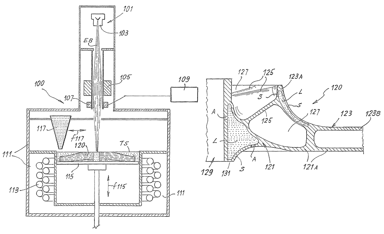
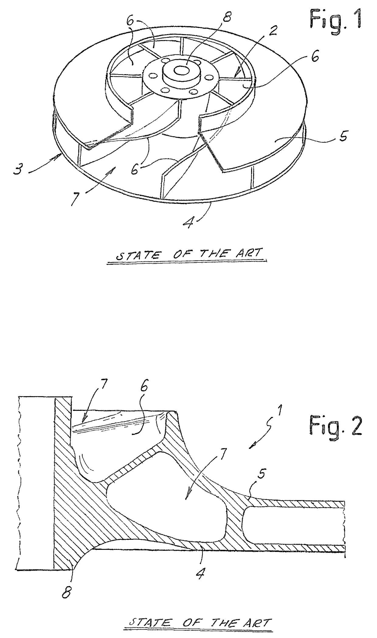
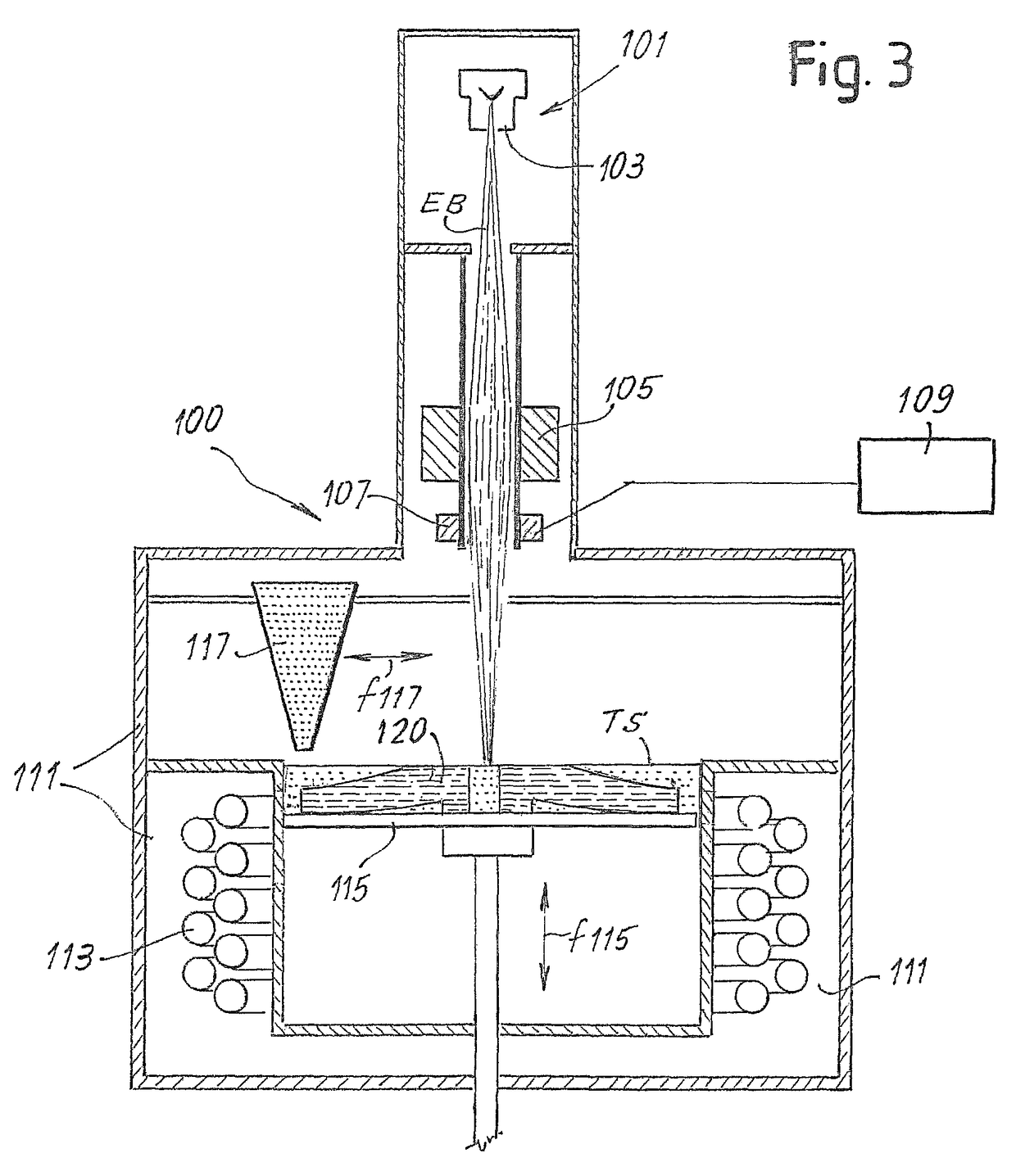
[0038]The following detailed description of the exemplary embodiments refers to the accompanying drawings. The same reference numbers in different drawings identify the same or similar elements. Additionally, the drawings are not necessarily drawn to scale. Also, the following detailed description does not limit the invention. Instead, the scope of the invention is defined by the appended claims.

[0039]Reference throughout the specification to “one embodiment” or “an embodiment” or “some embodiments” means that the particular feature, structure or characteristic described in connection with an embodiment is included in at least one embodiment of the subject matter disclosed. Thus, the appearance of the phrase “in one embodiment” or “in an embodiment” or “in some embodiments” in various places throughout the specification is not necessarily referring to the same embodiment(s). Further, the particular features, structures or characteristics may be combined in any suitable manner in one...


PUM

PropertyMeasurementUnit
lattice structureaaaaaaaaaa
mechanical strengthaaaaaaaaaa
thermal stressaaaaaaaaaa

Abstract

A method of manufacturing a turbo-machine impeller, which includes a hub and a plurality of blades, using powder material in an additive-manufacturing process. The method includes: applying energy to the powder material by way of a high energy source, and solidifying the powder material. At least one bulky portion of the hub is irradiated such that the powder material solidifies in a lattice structure surrounded by an outer solid skin structure enclosing the lattice structure.

Description

FIELD OF THE INVENTION[0001]Embodiments of the present disclosure relate to manufacturing of turbo-machine impellers, such as impellers for centrifugal compressors, centrifugal pumps or turboexpanders, and more specifically, manufacturing of turbo-machine impellers by additive-manufacturing-type production processes.DESCRIPTION OF THE RELATED ART[0002]Turbo-machine impellers, for centrifugal compressors or centrifugal pumps for example, are components of complex geometry. FIG. 1 illustrates a perspective view of an exemplary centrifugal compressor impeller. FIG. 2 shows an exemplary cross-section along a radial plane of a portion of a shrouded compressor impeller.[0003]The impeller, designated 1 as a whole, comprises an inlet 2 and outlet 3. The flow passage for the gas to be compressed extending from the inlet 2 to the outlet 3 is formed between a hub 4 and a shroud 5. Blades 6 are arranged between the hub 4 and the shroud 5. Between adjacent blades 6, flow vanes 7 are formed, exte...

Claims


Application Information

Patent Timeline
Patent Type & Authority Patents(United States)
IPC IPC(8): F01D5/18B22F5/04B23K26/342F01D5/14B22F3/105B22F5/00B22F5/10F04D29/02F04D29/28B23K15/00B23K101/00
CPCF01D5/18B22F5/009B22F5/04B22F5/10B23K15/0006B23K15/0086B23K26/342F01D5/147F04D29/023F04D29/284B22F3/1055Y02P10/295B23K2201/001F05D2230/22F05D2230/31F05D2300/171F05D2300/174F05D2300/175F05D2300/608B23K2101/001Y02P10/25B22F12/41B22F10/28B22F12/44B22F12/49B22F10/36B22F12/10B22F10/73B22F10/385B22F10/32B33Y80/00B22F3/105B22F10/00
Inventor TOZZI, PIERLUIGIGIOVANNETTI, IACOPOMASSINI, ANDREA
Owner NUOVO PIGNONE TECH SRL
Why Eureka
Try Eureka