Wind Power Generator

a wind power generator and wind power technology, applied in the direction of electric generator control, machines/engines, sustainable buildings, etc., can solve the problems of inability to obtain a stronger wind pressure with a smaller, restricted wind force rotation of the vanes, and inability to obtain wind force, etc., to achieve a larger driving force, increase the effect of efficient windward area and large amount of electricity

Inactive Publication Date: 2007-01-18
CHEN SHIH H
View PDF7 Cites 45 Cited by
  • Summary
  • Abstract
  • Description
  • Claims
  • Application Information

AI Technical Summary

Benefits of technology

[0007] The present invention is to solve the above problems. To avoid the problems, in the present invention, the wind power generator is re-designed to have a plurality of vanes therein. With this arrangement, the efficient windward area is increased, so that the driving force becomes larger and thus a larger amount of electricity can be generated.
[0008] The present invention is directed to an improved wind power generator, which comprises a cover, a front nose cone, a rear nose cone and a vane unit. When the wind enters the passage formed between the curved surface of the front nose cone and the front portion of the curved air-guiding portion of the cover, the wind speed is accelerated due to the narrowing of the flowing path, thereby to generate a larger kinetic energy to cause the rotation of the vane unit. In this way, the generator within the rear nose cone obtains a greater capacity of generating electricity. Further, the generator can be still activated even under a lower wind speed.

Problems solved by technology

Therefore, when the wind flows in the wind-collecting partitions, it flows through each wind-collecting partition smoothly, and thus the rotation of the vanes is restricted by the strength of the wind force.
Therefore, a compressed wind force cannot be obtained between each wind-collecting partition, and it is impossible to obtain a stronger wind pressure with a smaller wind force, which causes the windward vanes cannot provide the electricity with a stable rotation speed.
Further, since the whole structure and the volume of the vane wheels are bulky, the windward vanes of the vane wheels should be driven by a wind with a certain wind speed.
If the wind speed is too low to drive the windward vanes or the windward vanes rotate too slowly, the wind power generator cannot stably generate the desired electric power.

Method used


Image

  • Wind Power Generator
  • Wind Power Generator
  • Wind Power Generator

Examples


Embodiment Construction

[0014] The technical contents and the detailed description of the present invention will be made with reference to the accompanying drawings.

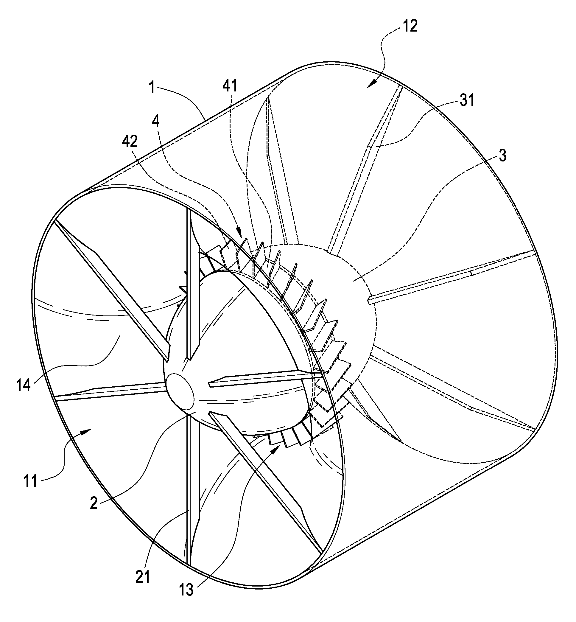
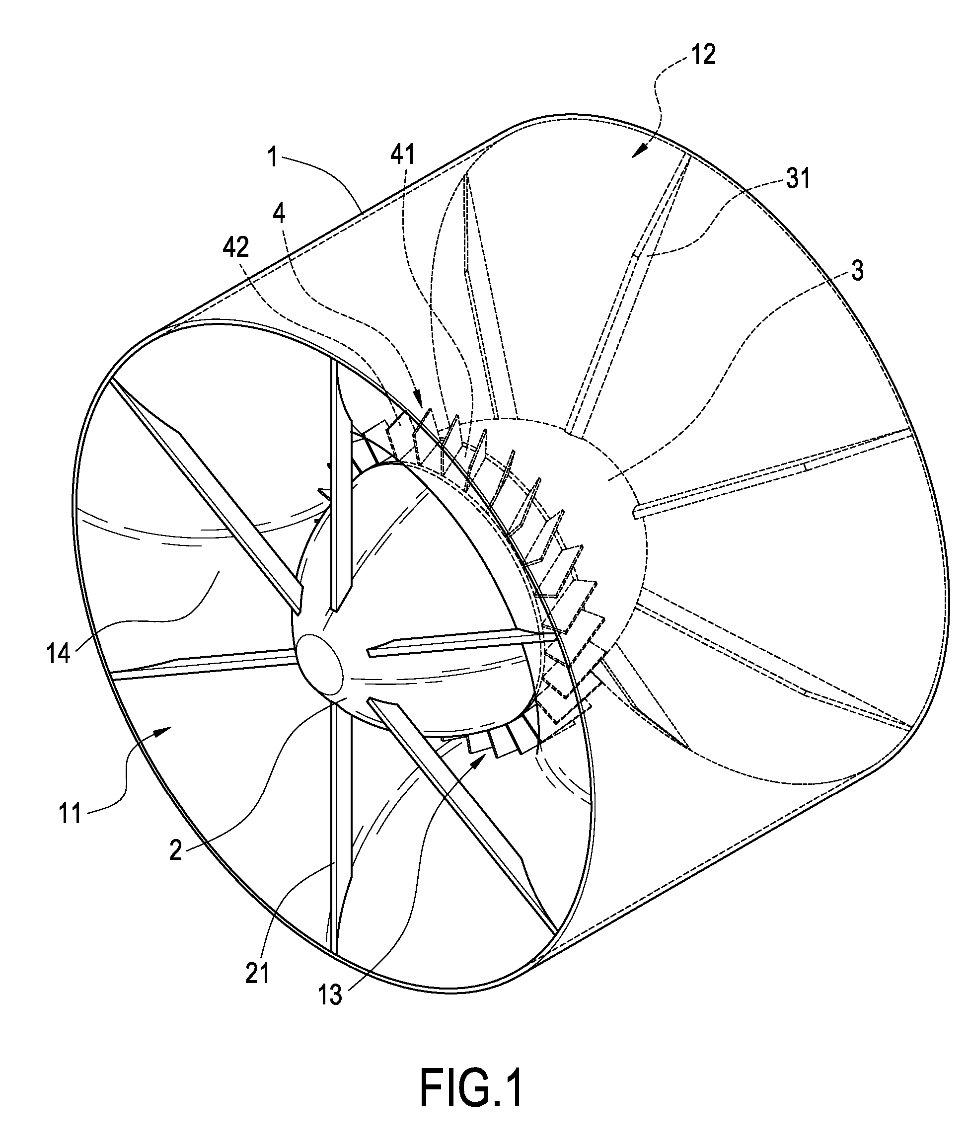
[0015]FIG. 1 is a perspective view showing the external appearance of the present invention, and FIG. 2 is a cross-sectional view of the present invention. As shown in the drawings, the present invention is directed to an improved wind power generator comprising a cover 1, a front nose cone 2, a rear nose cone 3 and a vane unit 4. The cover 1 is used to cooperate with the front nose cone 2 and the rear nose cone 3 to increase the efficient windward area. The airflow can be accelerated when passing through the narrowed flowing path, thereby to also increase the kinetic energy. In this way, the vane unit 4 can generate a larger kinetic energy and thus to obtain a greater capacity for generating electricity.

[0016] The cover 1 has a curved air-guiding portion 14 therein. The curved air-guiding portion 14 makes both ends of the cover 1 to form wid...


PUM


Abstract

A wind power generator includes a cover, a front nose cone, a rear nose cone and a vane unit. The cover has a curved air-guiding portion. The front nose cone and the rear nose cone have a plurality of supporting pillars fixedly connected to the front portion and rear portion of the inner wall of the cover, respectively. The vane unit is provided between the front nose cone and the rear nose cone. After the wind enters the passage formed between the curved surface of the front nose cone and the front portion of the curved air-guiding portion of the cover, the wind speed is accelerated due to the narrowing of the flowing path, thereby to generate a larger kinetic energy to cause the rotation of the vane unit. In this way, the generator within the rear nose cone obtains a greater capacity of generating electricity. Further, the generator can be still activated even under a lower wind speed.

Description

BACKGROUND OF THE INVENTION [0001] 1. Field of the Invention [0002] The present invention relates to a wind power generator, and in particular to a wind power generator having a plurality of vanes. [0003] 2. Description of Prior Art [0004] The conventional wind power generator disclosed in Taiwan Patent Publication No. M250048 utilizes the wind energy of the wind flow and converts the wind energy into the available electric energy. Such conventional wind power generator comprises a base, a structural frame provided upright on the base, a plurality of partitions provided in the structural frame for cooperating with the structural frame to define a plurality of comb-like wind-collecting partitions, each wind-collecting partition having a windward port for the entrance of the wind flow and a leeward port for the exhaust of the wind flow, and a plurality of windward vane wheels correspondingly provided in the plurality of wind-collecting partitions. Each windward vane wheel includes a h...

Claims


Application Information

Patent Timeline
Patent Type & Authority Applications(United States)
IPC IPC(8): F03D9/00H02P9/04F03D1/00F03D1/04
CPCF03D1/04F05B2240/13Y02E10/725Y02B10/30F05B2240/133Y02E10/72F03D9/25
Inventor CHEN, SHIH H.
Owner CHEN SHIH H
Why Eureka
Try Eureka