Method and apparatus for adaptive channel reduction for parallel imaging

a parallel imaging and channel reduction technology, applied in magnetic measurements, instruments, measurement devices, etc., can solve the problems of affecting the operation of the mr scanner. , to achieve the effect of reducing the time consumption of parallel reconstruction with 32 channels, and reducing the time consumption of parallel reconstruction

Inactive Publication Date: 2007-01-18
INVIVO CORP
View PDF25 Cites 36 Cited by
  • Summary
  • Abstract
  • Description
  • Claims
  • Application Information

AI Technical Summary

Problems solved by technology

In parallel imaging methods, however, the system load increases greater than linearly with the number of channels, where system load refers to the computations required to process the signals from the channels.
Unfortunately, for a large field of view image, significant information can be lost when the channels are turned off to reduce reconstruction load.
Parallel reconstruction with 32 channels is currently too time consuming for 3D data sets to be easily performed on MR scanners.
Further increases in scanner computation power may eventually obviate the need for channel compression.
Dynamic compression can also carry a low application risk, because it simulates a coil with fewer channels rather than fundamentally changing the reconstruction path.

Method used


Image

  • Method and apparatus for adaptive channel reduction for parallel imaging
  • Method and apparatus for adaptive channel reduction for parallel imaging
  • Method and apparatus for adaptive channel reduction for parallel imaging

Examples


example 1

Implementation of Selectable Mode Compression

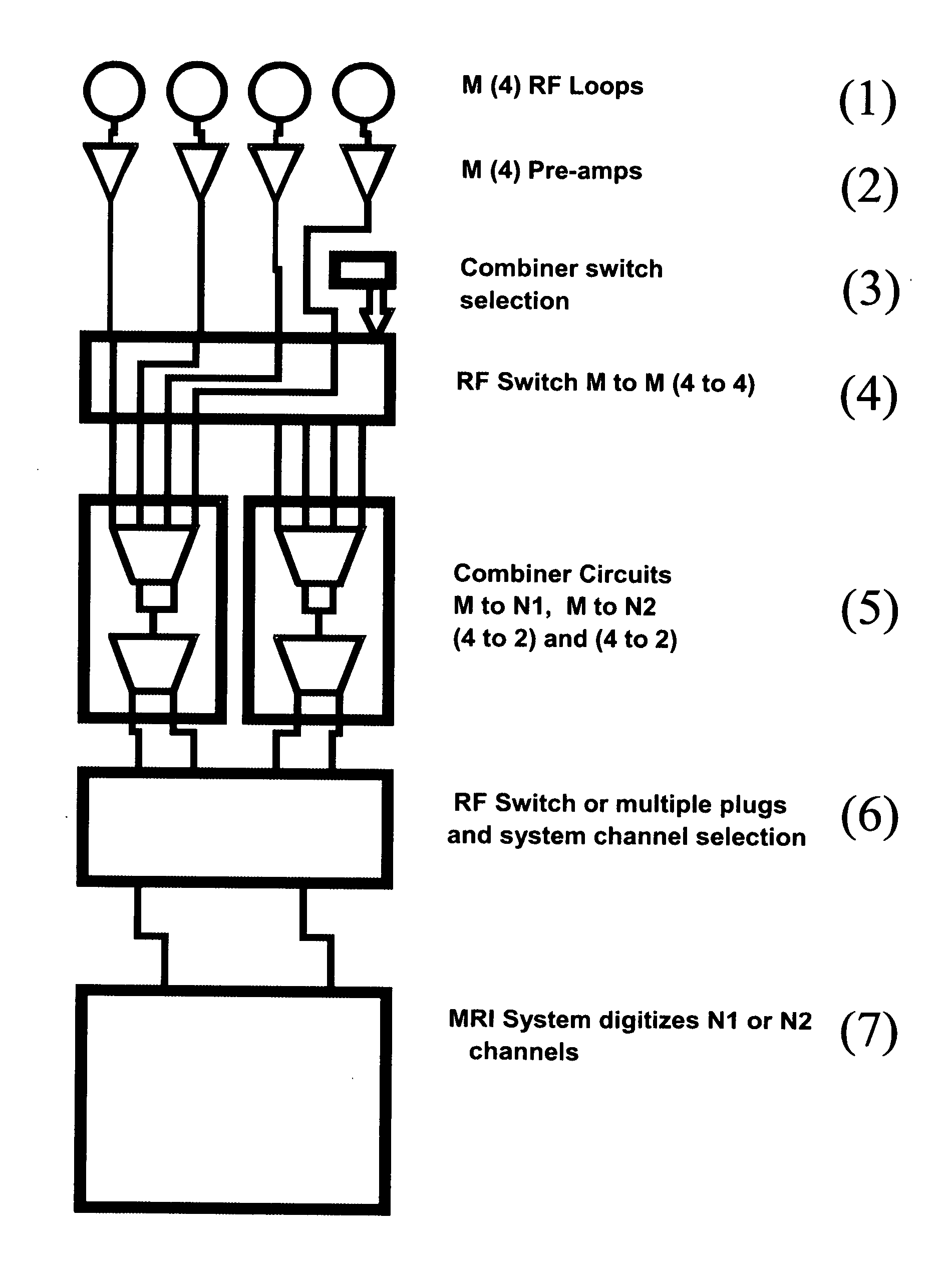
[0064] A specific embodiment of the subject invention pertaining to Selectable Mode Compression, as described above, employs a 32 channel coil. In this example, referring to FIG. 4, the subject process is described with respect to an embodiment employing 4 RF elements and producing 4 channel signals such that M=L and a channel signal is produced for each RF element signal.[0065] 1. Analog MR signals are acquired from all L RF loop antennae. [0066] 2. M signals are pre-amplified. [0067] 3. A signal is sent to the RF switch based on the main PE direction of the scan. [0068] 4. The RF switch routes all M channel signals to one of the combiner circuits. [0069] 5. The selected combiner circuit compresses the M channel signals to N channel signals. [0070] 6. The selected channels are routed to the system. [0071] 7. The MR system digitizes and reconstructs N channel signals.

example 2

Implementation of Software Computed Sensitivity Based Combination

[0072] Referring to FIG. 5, a specific embodiment of the subject invention, as taught in this example, can incorporate the following steps, so as to implement an adaptive combiner in software. There are 4 RF elements and 4 channel signals produced from the 4 RF elements such that M=L and a channel signal is produced for each RF channel signal. [0073] 1. Acquire L RF signals from the coil and produce M channel signals. [0074] 2. Pre-amplify all M signals and output to system channels. [0075] 3. Digitize all M signals. [0076] 4. Estimate the M channel sensitivity map. [0077] 5. Compute an M to N channel combiner matrix, Q, from the low resolution sensitivity map information, wherein N≦M. [0078] 6. Apply the combiner to the data readouts to create information from a synthetic N channel coil. [0079] 7. Reconstruct N channels with a standard parallel imaging algorithm. If a separate sensitivity map is used, the combiner ma...


PUM


Abstract

The subject invention pertains to method and apparatus for parallel imaging. The subject method can be utilized with imaging systems utilizing parallel imaging techniques. In a specific embodiment, the subject invention can be used in magnetic resonance imaging (MRI). A specific embodiment of the subject invention can reduce parallel reconstruction CPU and system resources usage by reducing the number of channels employed in the parallel reconstruction from the M channel signals to a lower number of channel signals. In a specific embodiment, sensitivity map information can be used in the selection of the M channel signals to be used, and how the selected channel signals are to be combined, to create the output channel signals. In an embodiment, for a given set of radio-frequency (RF) elements, an optimal choice of reconstructed channel modes can be made using prior view information and/or sensitivity data for the given slice. The subject invention can utilize parallel imaging speed up in multiple directions.

Description

CROSS-REFERENCE TO RELATED APPLICATION [0001] The present application claims the benefit of U.S. Provisional Application Ser. No. 60 / 678,559, filed May 6, 2005, which is hereby incorporated by reference herein in its entirety, including any figures, tables, or drawings.BACKGROUND OF INVENTION [0002] With respect to parallel imaging in fields such as Magnetic Resonance Imaging (MRI), typical array reconstructions improve image signal-to-noise (SNR) by adding more radio-frequency (RF) array channels. In parallel imaging methods, however, the system load increases greater than linearly with the number of channels, where system load refers to the computations required to process the signals from the channels. It is often desirable to reduce the system load for faster reconstruction time or refresh rate, or to permit more complex reconstruction methods within existing system and user limits. Hardware requirements and software sophistication may also be reduced with fewer array channels. ...

Claims


Application Information

Patent Timeline
Patent Type & Authority Applications(United States)
IPC IPC(8): G01V3/00
CPCG01R33/5611
Inventor AKAO, JAMESDUENSING, G. RANDYHUANG, FENG
Owner INVIVO CORP
Why Eureka
Try Eureka