Printhead with RFID antenna

a printing head and antenna technology, applied in the field of printing heads, can solve the problems of limiting the rf power that may be emitted by a separate printing head antenna, and achieve the effects of reducing power, reducing battery life, and reducing the cost of printing

Inactive Publication Date: 2007-01-18
INTERMEC IP
View PDF10 Cites 29 Cited by
  • Summary
  • Abstract
  • Description
  • Claims
  • Application Information

AI Technical Summary

Benefits of technology

[0007] The present invention is a print head with a built-in antenna. The built-in antenna allows for close proximity between the media and the antenna, particularly as the media passes under the print head. By embedding the RFID antenna in the print head potential interference is eliminated, as is the crosstalk between the smart labels. The built-in antenna at the print station allows for RF writing and printing at the same time.
[0008] The close proximity of the antenna to the RFID tag also allows for reduced power, which is an advantage in portable devices that often have limited battery life. Further, having a RFID antenna built in to the print head, allows for the printer to be smaller. Further, the printer assembly and repairs are quicker because there is no need for an additional patch antenna component.

Problems solved by technology

Due to space constraints and mechanical restriction, especially in small portable units, the placement of the separate patch antenna must take into consideration the size, length and transponder insert location within the smart label.
However, there are government regulatory guidelines that typically limit the RF power that may be emitted by a separate patch antenna.

Method used


Image

  • Printhead with RFID antenna
  • Printhead with RFID antenna
  • Printhead with RFID antenna

Examples


Embodiment Construction

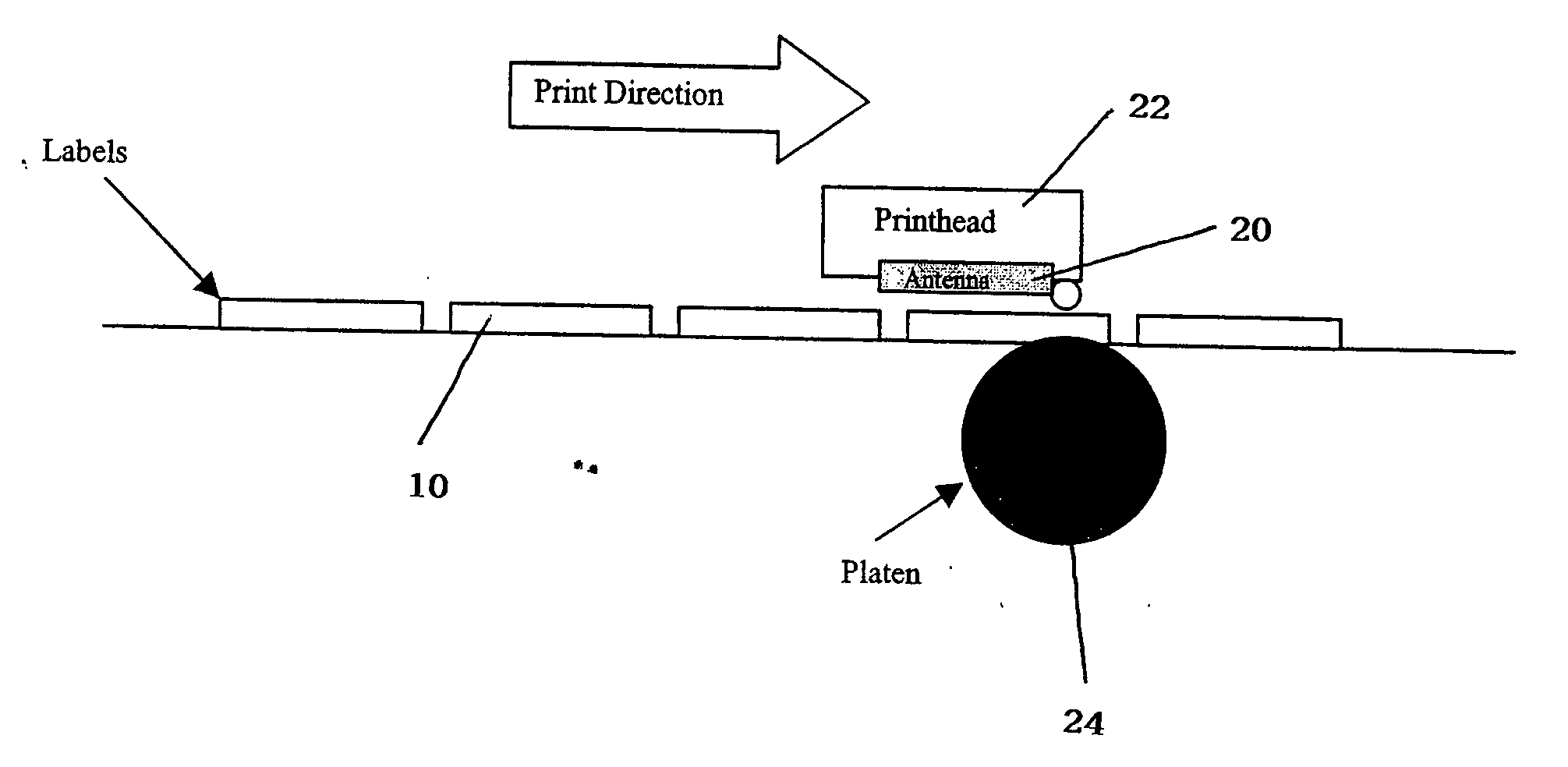
[0011] Smart labels or tags are labels or lags that have an embedded radio frequency transponders (known as RFID tags, inserts, insets or inlays) or an RFID tag laminated or otherwise applied to one surface. RFID tags generally include an antenna and integrated memory circuit with read / write capability. RFID tags are used to store digital information, such as all electrically erasable programmable read-only memory (EEPROM) or similar electronic information. Active RFID tags include their own radio transceiver and power source, such as a battery, and are generally sealed within a molded plastic housing or button. Passive RFID tags are energized to transmit and receive data by an electromagnetic field and do not include a radio transceiver or power source. As a result passive RFID tags are small, but they have a limited range, resolution and data storage capacity.

[0012] RFID tags can be laminated to and / or inserted into paper or synthetic label / tag stock. Label stock is typically bac...


PUM


Abstract

A printhead with a built-in antenna. The built-in antennaa allows for close proximity between the media and the antenna, particularly as media passes under the printhead. The RFID antenna embedded in the print head eliminates the potential interference and crosstalk between the smart labels. The built-in antenna at the print station allows for RF writing and printing at the same time. The close proximity of the antenna to the RFID tag also allows for reduced power, which is an advantage in portable devices that often have limited battery life. Having a RFID antenna built in to the print head, also allows for a printer with smaller dimensions. Further, the printer assembly and repairs are quicker because there is no need for an additional patch antenna component.

Description

[0001] This application claims the benefit of U.S. Provisional Application No. 60 / 657,879 filed 1 Mar. 2005 and entitled Print Head with RFID Antenna.BACKGROUND OF THE INVENTION [0002] 1. Field Of The Invention [0003] The present invention relates to printers. More specifically it relates to an antenna built into a printhead for reading and / or writing to smart labels. [0004] 2. Description Of Related Art [0005] Prior art RFID labels were written to using separate patch antennas located above the media path, the antenna itself is either in the printer or remote from the printer. Using a separate patch antenna has several disadvantages. Due to space constraints and mechanical restriction, especially in small portable units, the placement of the separate patch antenna must take into consideration the size, length and transponder insert location within the smart label. Further, if the patch antenna is located at a remote location from the print head, the sequence of printing and encodin...

Claims


Application Information

Patent Timeline
Patent Type & Authority Applications(United States)
IPC IPC(8): G08B13/14
CPCG06K7/0008H01Q1/2216G06K17/0025G06K7/10316
Inventor CONWELL, KEVINADAMS, MATT
Owner INTERMEC IP
Why Eureka
Try Eureka