Black level uniformity correction method

a correction method and black level technology, applied in the field of image processing, can solve problems such as non-uniform luminance, non-uniform luminance, and undesirable shifts in tint and shading

Inactive Publication Date: 2007-01-18
EASTMAN KODAK CO
View PDF4 Cites 17 Cited by
  • Summary
  • Abstract
  • Description
  • Claims
  • Application Information

AI Technical Summary

Problems solved by technology

In spite of their growing acceptance, however, both thin-film transmissive LC display panels and miniaturized liquid crystal on silicon (LCOS) devices often exhibit luminance non-uniformity, particularly when the system is set to its darkest levels.
This non-uniformity in luminance can be particularly perceptible toward the edges and corners of the display field and is often accompanied by undesirable shifts in tint and shading, particularly with an image having low luminance values.
As yet a further complication, the relative chromaticity of pixels may vary with their luminance level.
Thus, differences in luminance may adversely impact color fidelity as well.
Among sources of this performance problem are imperfections in the components of the optical path, including imperfections within the LCD itself, and thermal effects acting on the components.
Because of its pervasive nature and complex combination of causes, this luminance non-uniformity problem has not yet been adequately addressed in many display apparatus designs.
Instead, many display designers and vendors simply take it as a “given” that such luminance non-uniformity is to be expected with these devices.

Method used


Image

  • Black level uniformity correction method
  • Black level uniformity correction method
  • Black level uniformity correction method

Examples


example values

[0082] The tables of FIGS. 9, 10, and 11 give example numerical values for pixels 1, 2, and 3 in the graph of FIG. 7, respectively. For each pixel, the black level correction value and threshold value 16 are identified, with equations used to obtain the actual values used according to the present invention.

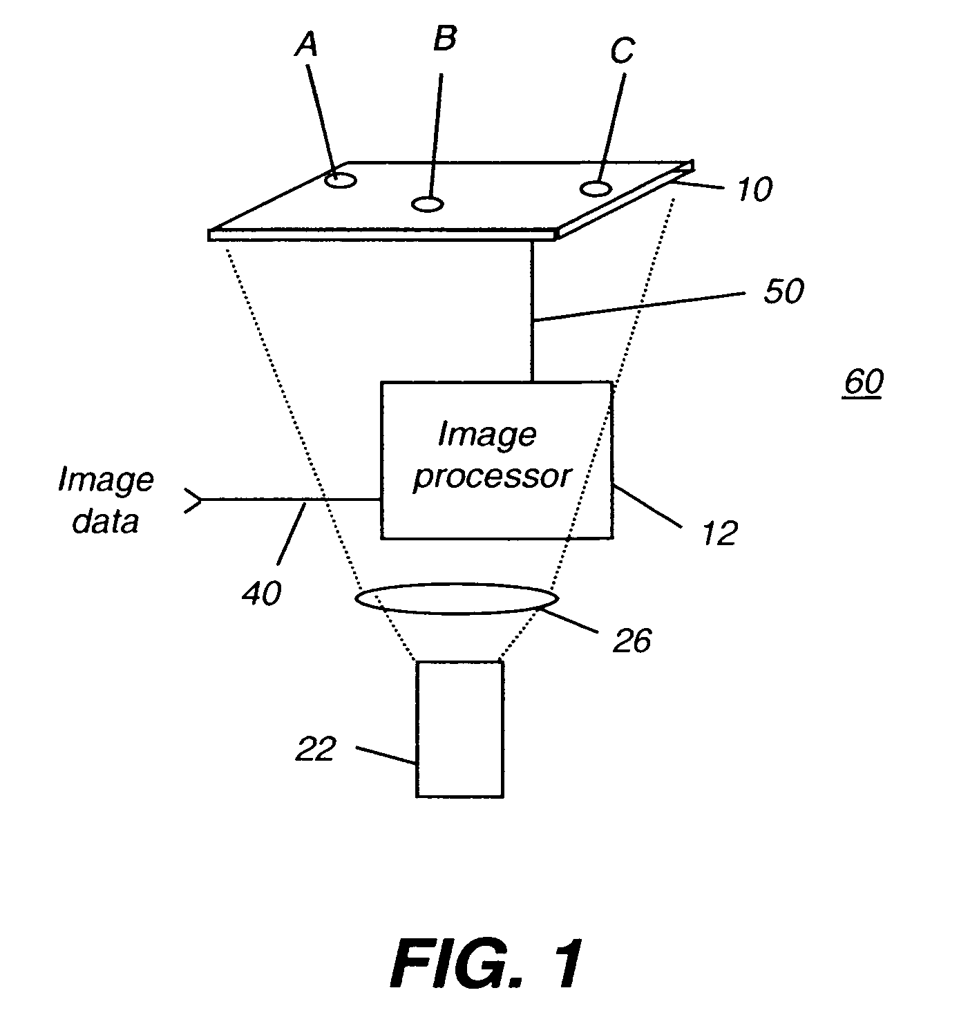
[0083] Taking the example of FIG. 9, the black level code value is 100. With reference again to FIG. 1, this means that when original code value 40 is 0, indicating the minimum luminance level or black level, image processor 12 transforms this value to provide a conditioned code value 50 of 100. With reference to FIG. 7, threshold value 16 is set at 128. Interpolation zone 18, then, applies for original code values 40 ranging from 1 to 127. Image processor 12 transforms these values to provide conditioned code values 50 calculating, for this example:

Round(100+92*(145−100) / (128−0))

Thus, image processor 12 transforms an original code value 40 of 64 to provide a conditioned code ...


PUM


Abstract

A method for improving liquid crystal spatial light modulator (10) uniformity is disclosed wherein an original code value (40) is obtained for a first pixel and a conditioned code value (50) is assigned to the first pixel. The conditioned code value is determined by characterizing the luminance response of a sample pixel of the spatial light modulator and defining an interpolation zone (18) for code values bounded between a minimum luminance code value and a threshold code value (16) for the sample pixel. The threshold value corresponds to a luminance level at which there is a generally linear relationship of luminance to code values. If the original code value lies within the interpolation zone, an interpolated value is calculated as the conditioned code value. The pixel of the spatial light modulator is modulated according to the conditioned code value.

Description

FIELD OF THE INVENTION [0001] The present invention generally relates to imaging apparatus and more particularly relates to a method for improving uniformity from an electronic display using a liquid crystal (LC) spatial light modulator. BACKGROUND OF THE INVENTION [0002] Thanks to continuing performance and yield improvements, increasing speeds, and higher pixel resolutions, liquid crystal (LC) spatial light modulator devices hold out considerable promise for expanded use in a range of display and projection apparatus. In spite of their growing acceptance, however, both thin-film transmissive LC display panels and miniaturized liquid crystal on silicon (LCOS) devices often exhibit luminance non-uniformity, particularly when the system is set to its darkest levels. This non-uniformity in luminance can be particularly perceptible toward the edges and corners of the display field and is often accompanied by undesirable shifts in tint and shading, particularly with an image having low ...

Claims


Application Information

Patent Timeline
Patent Type & Authority Applications(United States)
IPC IPC(8): G09G3/34
CPCG09G3/001G09G3/3611G09G5/02H04N9/312G09G2320/0238G09G2320/0285G09G2320/0233
Inventor STOOPS, JAMES
Owner EASTMAN KODAK CO
Why Eureka
Try Eureka