
System and method for fast template matching by adaptive template decomposition

a template and adaptive technology, applied in the field of machine vision inspection systems, can solve the problems of insufficient template matching accuracy, known types of template matching using integral projection lack robustness, and excessive slowdown of matching process, so as to reduce and/or approximate the optimal processing time, the effect of high accuracy template position results

Inactive Publication Date: 2007-01-18
MITUTOYO CORP
View PDF9 Cites 45 Cited by
  • Summary
  • Abstract
  • Description
  • Claims
  • Application Information

AI Technical Summary

Benefits of technology

[0008] A method of template matching that combines integral projection techniques with a novel template decomposition technique is provided. The novel template decomposition technique subdivides the defined template into a number of segments that are sufficient to ensure robust template matching and high accuracy template position results for a wide variety of workpiece features, while doing so with reduced and / or approximately optimum processing time.

Problems solved by technology

This may result in an undue slowdown of the matching process particularly for large templates, which are becoming common as the camera resolution increases.
However, known types of template matching using integral projection lack robustness when certain types of patterns are to be matched.
In particular, the loss of pattern information resulting from the formation of integral projections may lead to erroneous or insufficiently accurate template matching.
Lack of template matching robustness and insufficiently accurate template position determination (that is, accurate determination of the workpiece feature that matches the template) are particular problems with respect to general-purpose precision machine vision inspection systems, which are expected to provide measurements that are accurate at the pixel or subpixel resolution level for a wide variety of workpiece features.

Method used


Image

  • System and method for fast template matching by adaptive template decomposition
  • System and method for fast template matching by adaptive template decomposition
  • System and method for fast template matching by adaptive template decomposition

Examples


Embodiment Construction

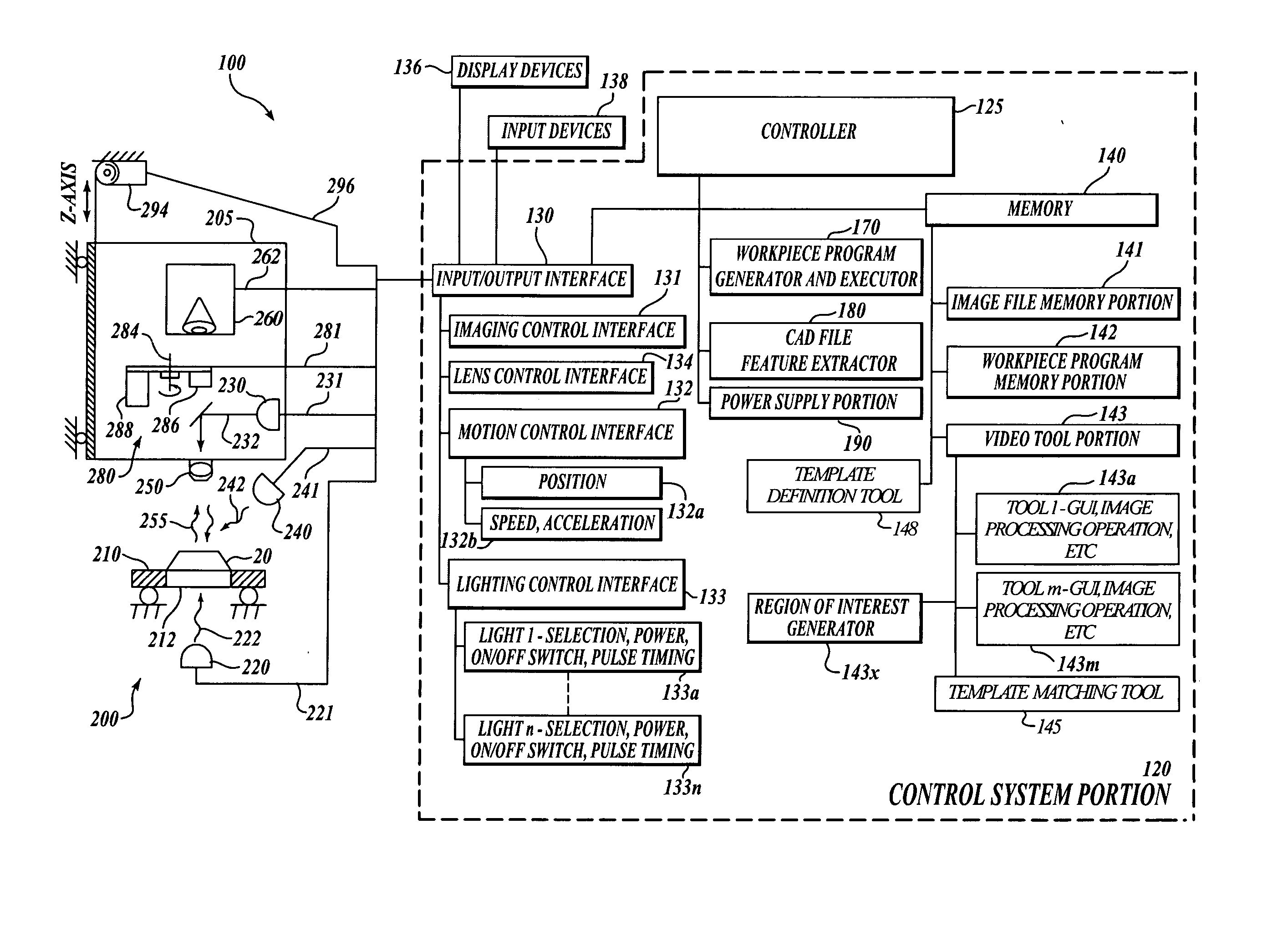
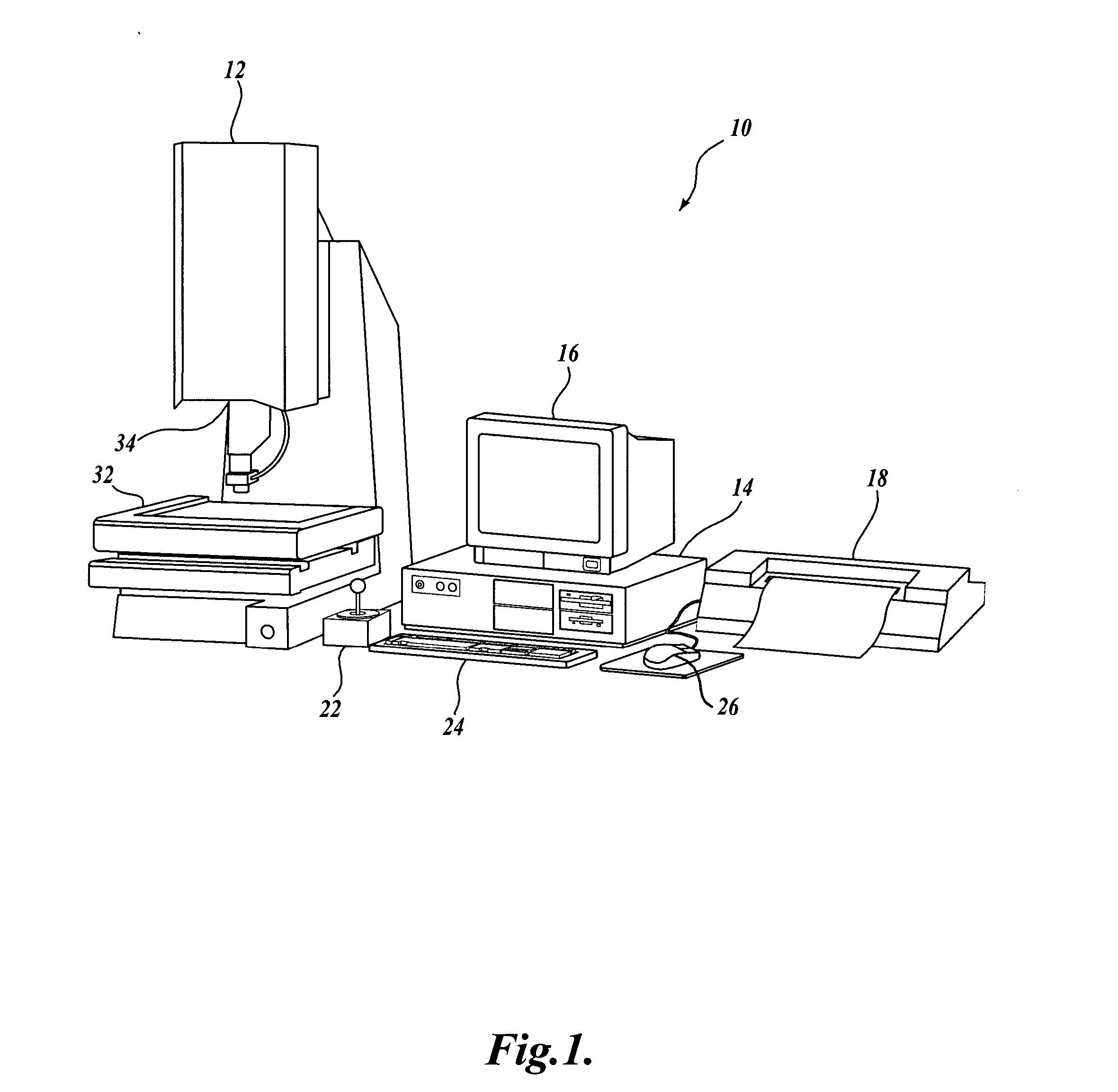
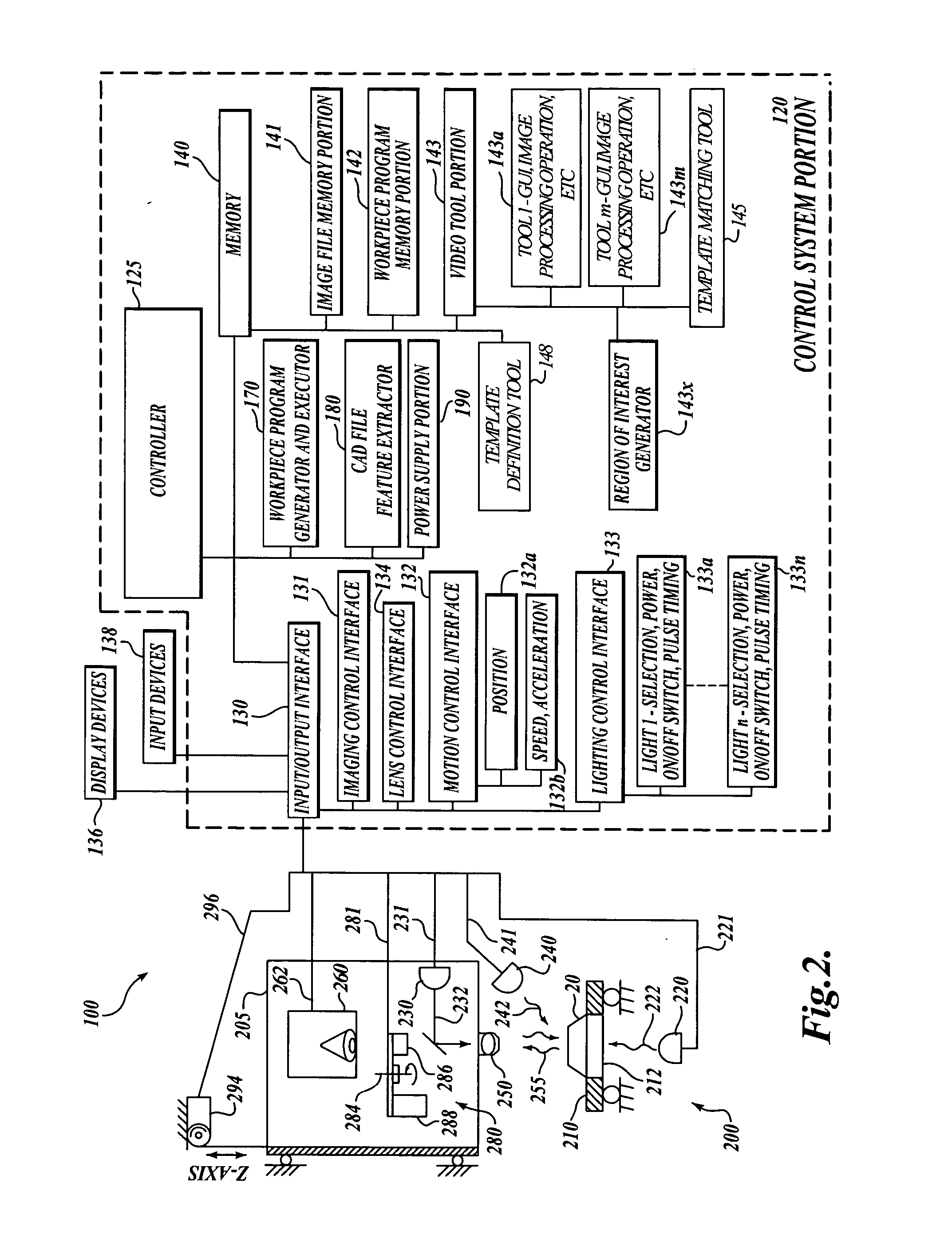
[0027]FIG. 1 is a block diagram of one exemplary machine vision inspection system 10 in accordance with the present invention. The machine vision inspection system 10 includes a vision measuring machine 12 that is operably connected to exchange data and control signals with a controlling computer system 14. The controlling computer system 14 is further operably connected to exchange data and control signals with a monitor 16, a printer 18, a joystick 22, a keyboard 24, and a mouse 26. The monitor or display 16, may display a user interface suitable for controlling and / or programming the operations of the machine vision inspection system 10.

[0028] The vision measuring machine 12 includes a moveable workpiece stage 32 and an optical imaging system 34 which may include a zoom lens or interchangeable lenses. The zoom lens or interchangeable lenses generally provide various magnifications for the images provided by the optical imaging system 34. The machine vision inspection system 10 i...


PUM


Abstract

A fast template matching method by adaptive template decomposition is provided. The template decomposition technique subdivides a template into a number of horizontal and / or vertical subdivisions and one-dimensional characterizations are determined for the subdivisions. The template decomposition may be adapted during learn mode operations of a general-purpose precision machine vision inspection system, with the support of corresponding user interfaces. The matching results for one or more template decomposition configurations may be evaluated by a user, or by an automatic decomposition configuration evaluation routine, to determine a configuration that provides a desirable trade-off between speed and matching position accuracy. Automatic workpiece inspection instructions may implement the configuration to repeatedly provide optimum speed versus accuracy trade-offs during run mode operations of the inspection system.

Description

FIELD OF THE INVENTION [0001] The invention relates generally to methods for operating a machine vision inspection system with a camera and stage that are movable relative to one another in multiple directions so as to scan and inspect selected features (or patterns) of a workpiece on the stage, and more particularly to systems and methods that adaptively decompose a 2D template (pattern) into multiple subdivisions and correlate them with a workpiece image for fast template matching and position determination (pattern search). BACKGROUND OF THE INVENTION [0002] Precision machine vision inspection systems (or “vision systems” in short) can be utilized to obtain precise dimensional measurements of inspected objects and to inspect various other object characteristics. Such systems may include a computer, a camera and optical system, and a precision stage that is movable in multiple directions so as to allow the camera to scan the features of a workpiece that is being inspected. One exe...

Claims


Application Information

Patent Timeline
IPC IPC(8): G06K9/00G06K9/62
CPCG06K9/4609G06V10/443
Inventor BRYLL, ROBERT K.
Owner MITUTOYO CORP
Learn More