Image-taking apparatus

Inactive Publication Date: 2007-01-18
FUJIFILM HLDG CORP +1
View PDF1 Cites 20 Cited by
  • Summary
  • Abstract
  • Description
  • Claims
  • Application Information

AI Technical Summary

Benefits of technology

[0011] In the first image-taking apparatus of the invention, light is emitted from the xenon tube when a shake detected before shooting is above a predetermined level whereas light is emitted from the LED when a shake detected before shooting is equal to or below the predetermined level. Therefore, it is possible to reduce blurriness of a subject image by use of the xenon tube even in a situation, for example, where a large shake is likely to occur in shooting by an inexperienced user, while reducing waiting time between one shooting and the next shooting by use of the LED requiring no charging time. Accordingly, the first image-taking apparatus of the invention is capable of reducing the waiting time between shootings as well as blurriness of subject image.
[0013] Because a subject image formed on the imaging device expands and contracts according to the focal length of the shooting lens, a blur of the subject image changes depending on the focal length of the shooting lens. Therefore, the first image-taking apparatus of the invention is additionally configured to select either the xenon-tube emission section or the LED emission section based on the focal length of the shooting lens so that blurriness of a subject image can be appropriately reduced.
[0020] In the second image-taking apparatus of the invention, light is emitted from the xenon tube when a blur detected before shooting is above a predetermined level whereas light is emitted from the LED when a blur detected before shooting is equal to or below the predetermined level. Therefore, it is possible to reduce not only blurriness caused by shakes of the image-taking apparatus but also blurriness caused by movements of a subject, while reducing the waiting time between shootings.
[0023] In an area where focusing is adjusted by the focus adjustment section, a subject image is sharply formed and therefore, a blur of the subject image is most likely to be observed. Also, this area usually receives more attention and the elimination of blur is desired most in this area. Because a blur of a subject image is detected in such a focus adjustment area, it is possible to reduce blurriness of a subject image in this area.
[0026] A face position recognized by the face recognition section usually receives more attention in a shooting angle of view and the elimination of blur is desired most in this position. Accordingly, it is possible to reduce blurriness of a subject image in an area where the elimination of blur is desired most by detecting a blur of a subject image in such a face position.
[0027] As described above, the invention realizes image-taking apparatus capable of reducing the waiting time between shootings as well as blurriness of a subject image.

Problems solved by technology

On the other hand, LEDs have such a drawback that the intensity of emission is lower than xenon tubes.
However, it is not realistic to provide a large number of LEDs in a shooting apparatus to attain the intensity of emission equal to that of a xenon tube in view of restrictions such as limited space.
However, during such a long emission time, movement of a shooting apparatus i.e. shake as well as blurring of a subject image due to movement of a subject are likely to frequently occur.

Method used


Image

  • Image-taking apparatus
  • Image-taking apparatus
  • Image-taking apparatus

Examples


first embodiment

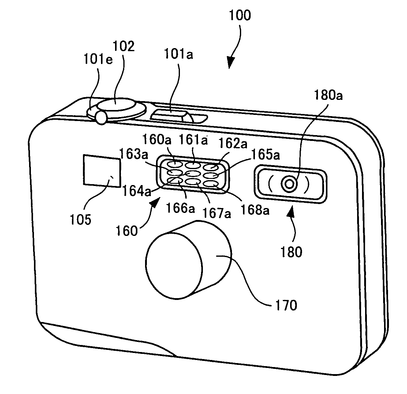
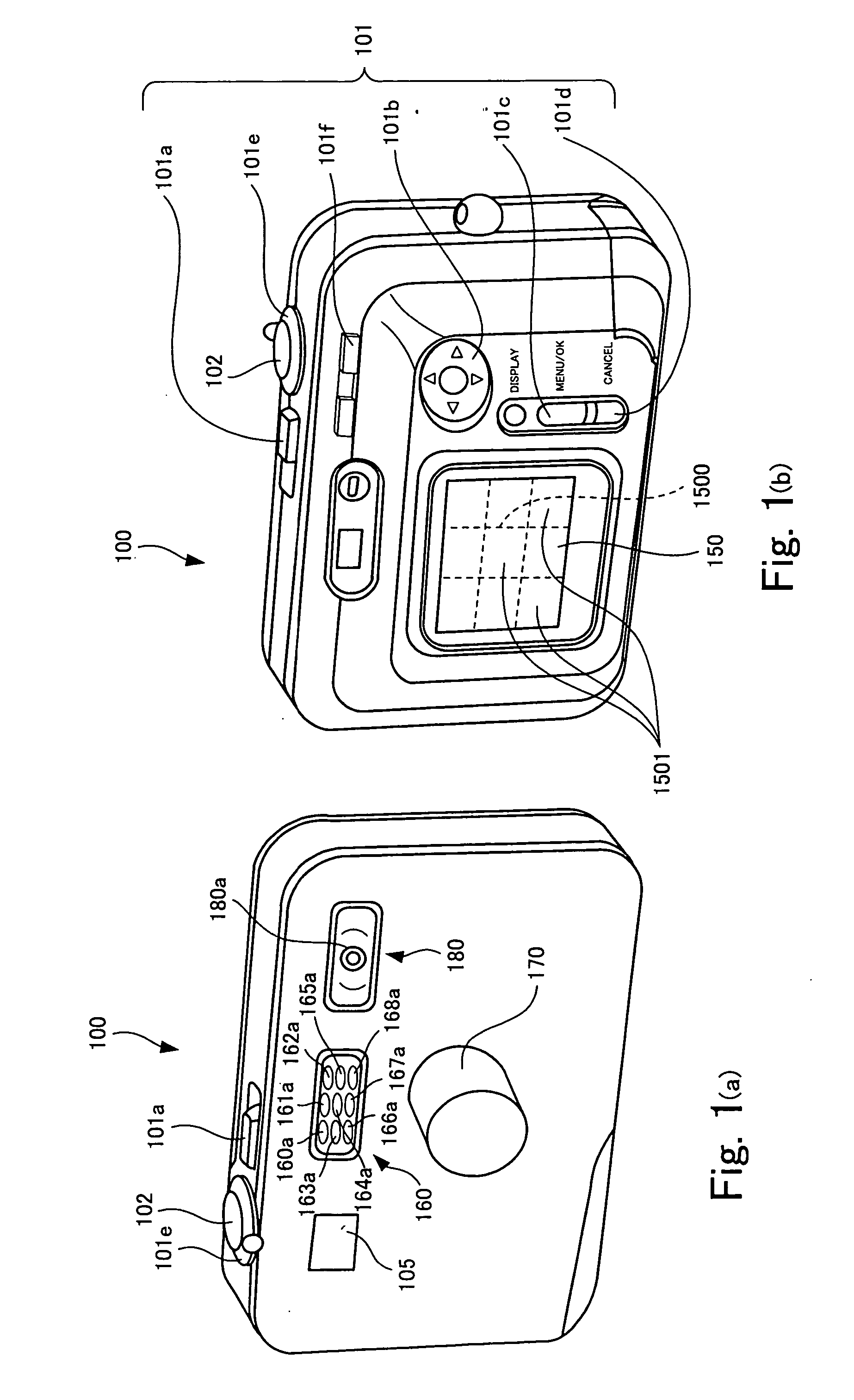
[0044] As shown in FIG. 1(a), a finder 105, an LED emission section 160 and a xenon-tube emission section 180 are disposed above the lens barrel 170 of the digital camera 100. The LED emission section 160 has LEDs 160a through 168a and irradiates a subject with fill light for shooting emitted from these LEDs. Although the digital camera 100 shown in FIG. 1(a) is provided with plural LEDs 160a through 168a, only one LED may be provided instead. The xenon-tube emission section 180 has a xenon tube 180a and irradiates a subject with fill light for shooting emitted from the xenon tube 180a, which light is relatively higher in intensity than the light from the LED emission section 160. Because the xenon tube 180a is capable of emitting light whose intensity is higher than the LEDs 160a through 168a, the xenon-tube emission section 180 can irradiate a subject with an appropriate amount of light required for exposure in a short time. In contrast, the LEDs 160a through 168a can be quickly r...

second embodiment

[0078]FIGS. 6, 7 and 8 are diagrams to describe a second embodiment according to the invention.

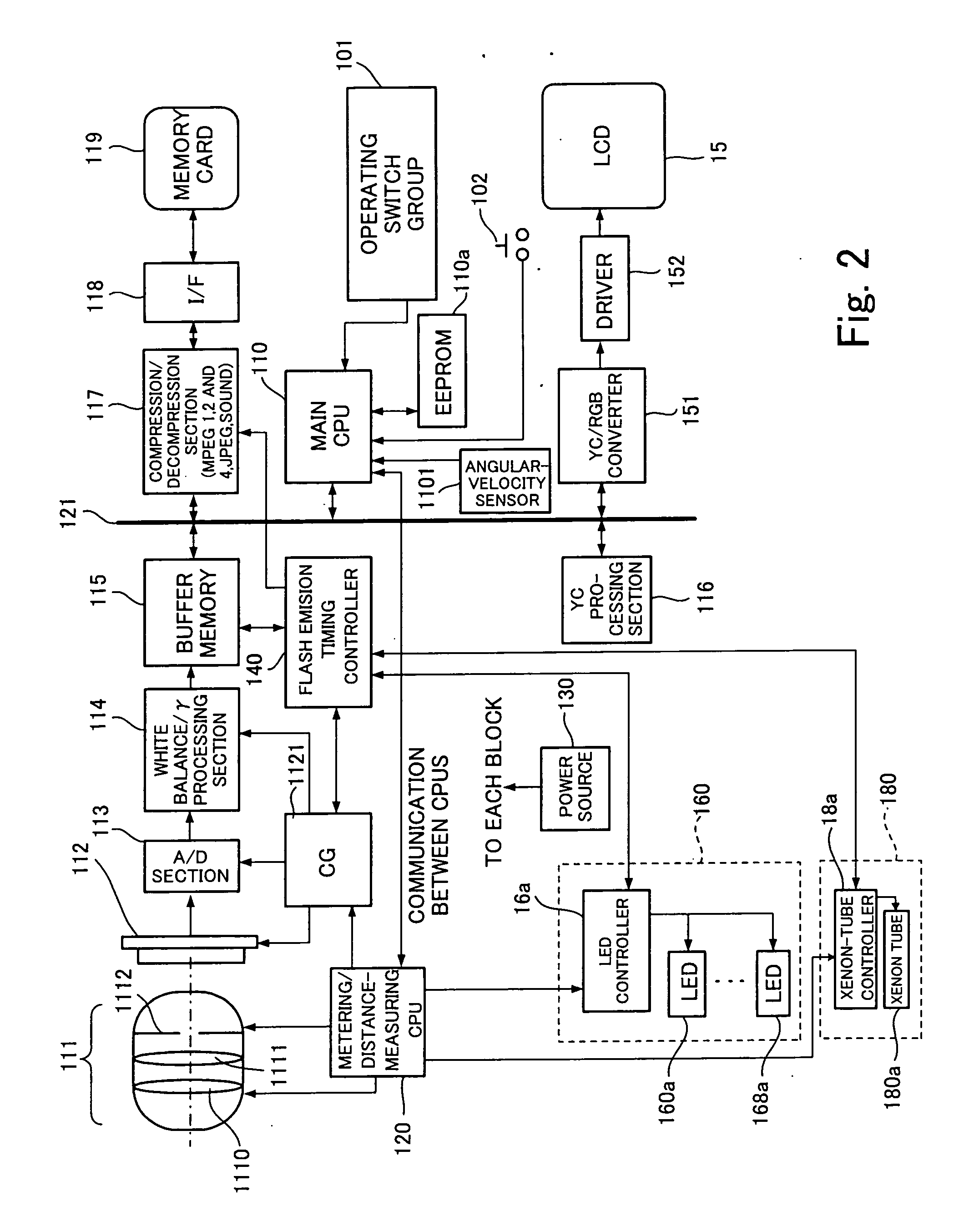
[0079]FIG. 6 is a block diagram illustrating the internal configuration of a digital camera according to the second embodiment.

[0080] The digital camera of the second embodiment is the same as the digital camera 100 of the first embodiment shown in FIG. 2 except that a motion vector detector 1103 is provided in place of the angular-velocity sensor 1101. The motion vector detector 1103 detects a subject-image movement formed on a CCD 112 by reading out image signals from a buffer memory 115 and comparing the read-out image signals with previously read-out image signals and outputs the result of the detection as a motion vector. What the motion vector detector 1103 detects here is a subject-image movement in an area designated by a main CPU 110. The main CPU 110 designates a distance-measurement area, i.e. AF area, selected as an area to be focused from among plural distance-measurement are...

third embodiment

[0090]FIGS. 9, 10 and 11 are diagrams showing a third embodiment according to the invention.

[0091]FIG. 9 is a block diagram illustrating the internal configuration of a digital camera according to the third embodiment.

[0092] The digital camera of the third embodiment is the same as the digital camera 100 of the first embodiment shown in FIG. 2 except that a face-recognition section 1105 and a motion vector detector 1107 for detecting a subject-image movement in an area including a face position detected by the face-recognition section 1105 are provided in place of the angular-velocity sensor 1101.

[0093] Since other elements and the appearance of the digital camera according to the third embodiment are the same as those of the first embodiment shown in FIGS. 1 and 2, the same reference characters as those of the first embodiment are used here and the description thereof will be omitted.

[0094]FIG. 10 shows distance-measurement areas 15011, 15012, 15013, 15014, 15015, 15016, 15017, ...


PUM


Abstract

An image-taking apparatus includes a LED emission section that irradiates a subject with light by causing a LED to emit the light and a xenon-tube emission section that irradiates a subject with light by causing a xenon tube to emit the light. The light from the xenon-tube emission section has higher intensity than the light from the LED emission section. The image-taking apparatus also includes a shake detection section that predicts a shake that will occur at shooting by detecting a shake before shooting. The image-taking apparatus also includes an emission control section that causes the xenon-tube emission section to irradiate a subject with light when the detected shake is above a predetermined level, and causes the LED emission section to irradiate a subject with light when the detected shake is equal to or below the predetermined level.

Description

BACKGROUND OF THE INVENTION [0001] 1. Field of the Invention [0002] The present invention relates to an image-taking apparatus that includes an imaging device and forms a subject image on the imaging device thereby generating image signals. [0003] 2. Description of the Related Art [0004] The emergence of blue light-emitting diodes has made it possible to generate white light with light-emitting diodes. As a result, there is a trend to replace incandescent lamps consuming a large amount of power with light-emitting diodes (LED) consuming a small amount of power for the purpose of reducing power consumption. Such a trend has been also seen in the field of digital cameras and the LEDs are replacing xenon tubes used for fill in shooting. LEDs require no charging of a capacitor because they are capable of emitting light with low voltage while xenon tubes require charging. Therefore, LEDs have such an advantage that the waiting time between one emission and the next emission is shorter th...

Claims


Application Information

Patent Timeline
IPC IPC(8): G03B17/00
CPCG03B15/03G03B2217/005H04N5/2354H04N5/23254H04N5/23258H04N5/2256H04N23/56H04N23/6811H04N23/6812H04N23/74
Inventor ENDO, HIROSHI
Owner FUJIFILM HLDG CORP
Why Eureka
Try Eureka