Balloon catheter

a balloon catheter and balloon technology, applied in balloon catheters, catheters, surgery, etc., can solve the problems of difficult to pass a wire through the stent structure, difficult to steer many types of catheters, and difficult to pass a stent after implantation

Inactive Publication Date: 2007-01-18
ABBOTT LAB INC
View PDF7 Cites 30 Cited by
  • Summary
  • Abstract
  • Description
  • Claims
  • Application Information

AI Technical Summary

Benefits of technology

[0018] When desired, one or more retaining sheaths that surround the balloon segments may be provided

Problems solved by technology

Since it can be difficult to steer many types of catheters, guide wires are often used to position the catheters.
In situations where the main or side branch has been stented and the stent is positioned over the bifurcation it migh

Method used


Image

  • Balloon catheter
  • Balloon catheter
  • Balloon catheter

Examples


Embodiment Construction

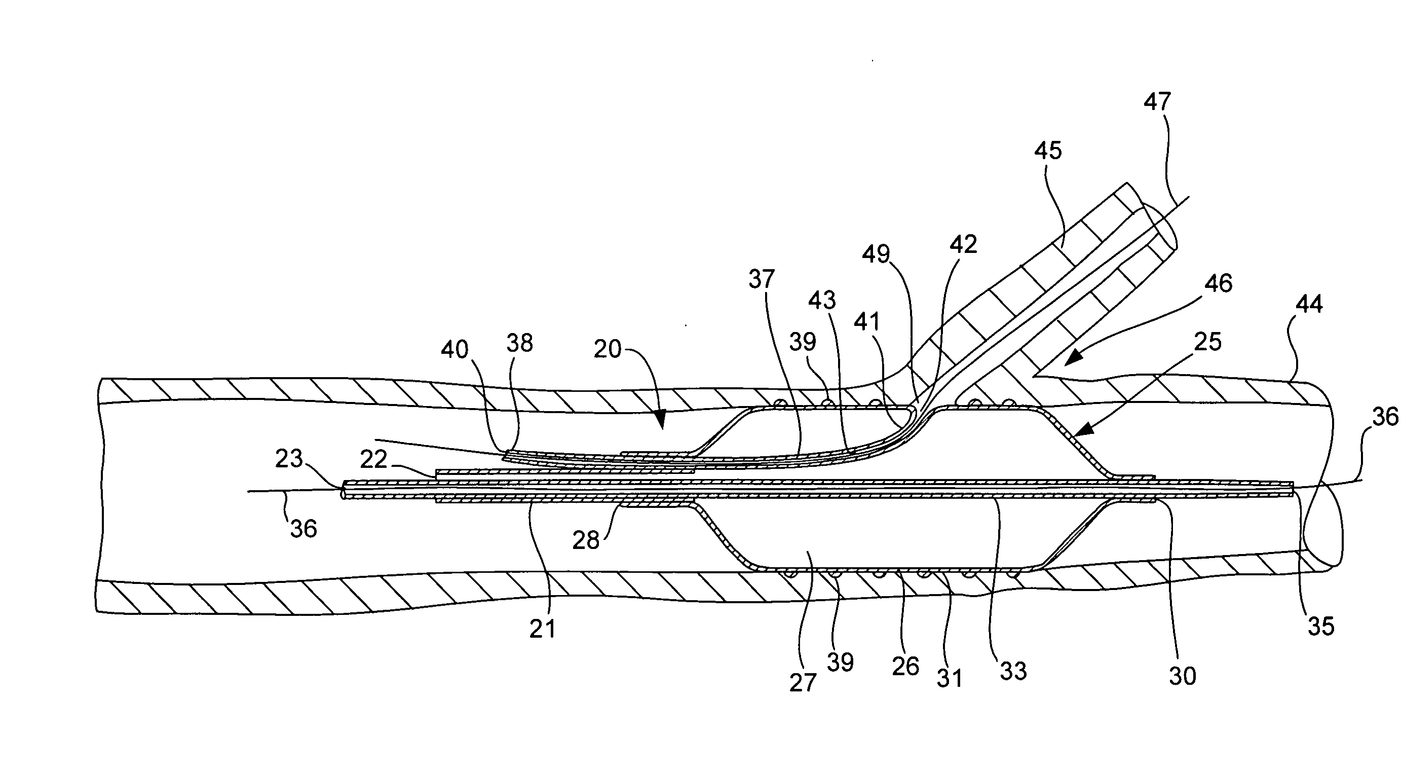
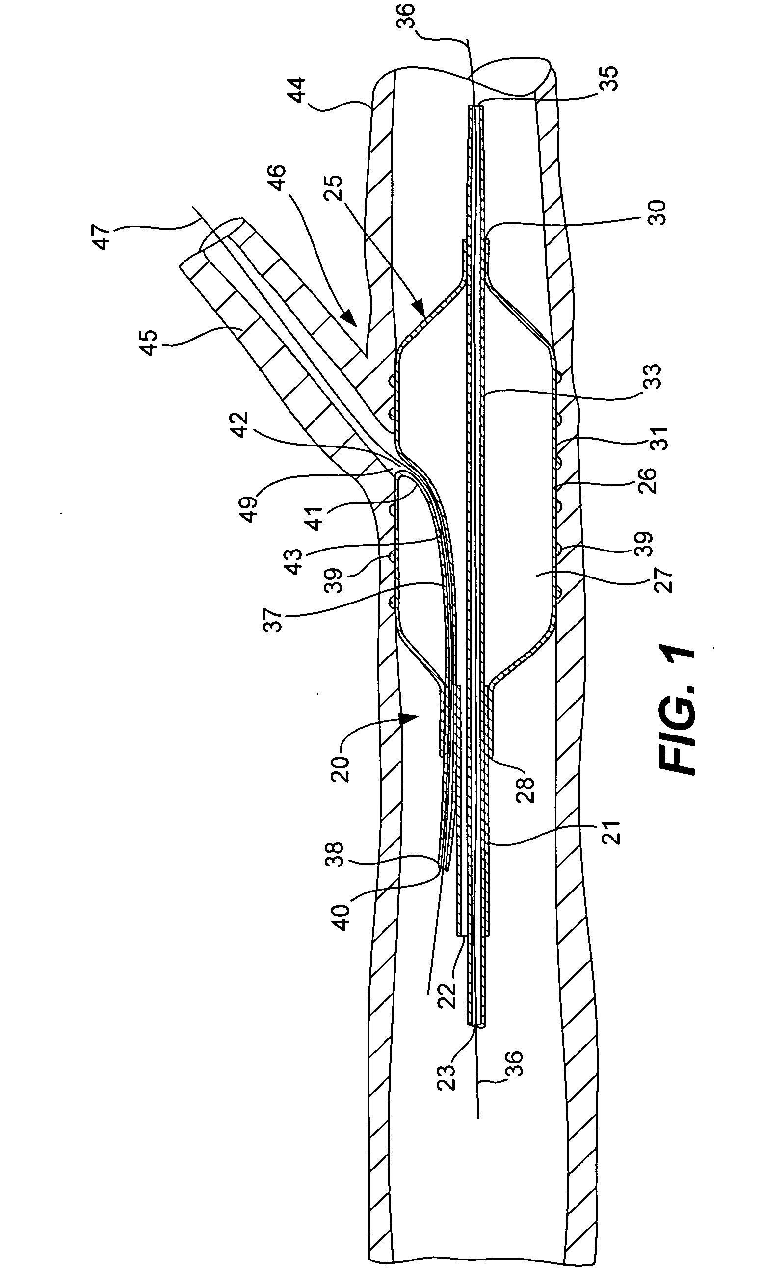
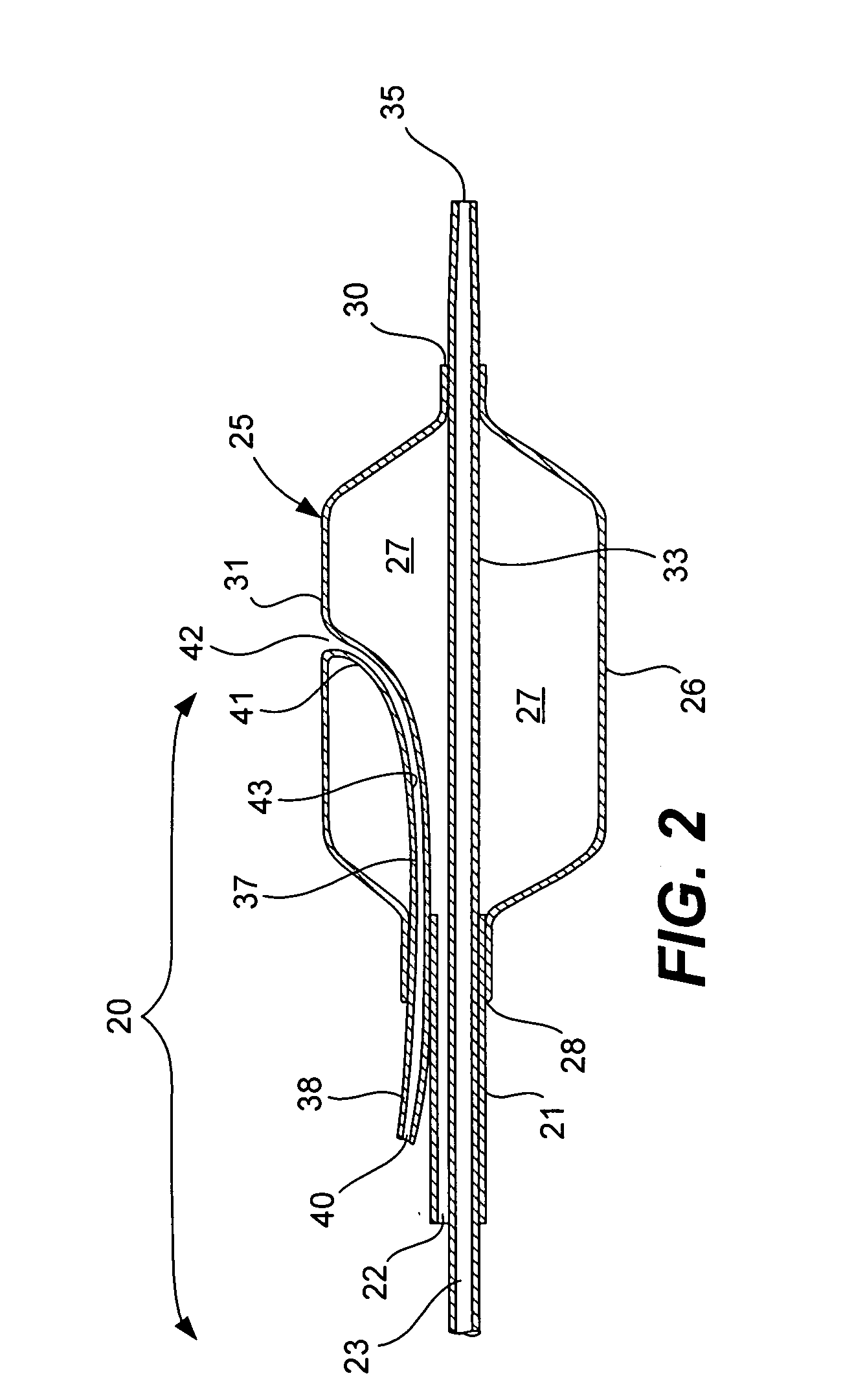
[0035] The present invention relates generally to catheters that are designed to permit a guide wire or other structure to be fed laterally from the region of an expandable working element. Such arrangements are believed to be particularly useful in devices that are intended for use in the vicinity of vessel bifurcations.

[0036] Referring now to FIGS. 1-3, a delivery catheter assembly, generally designated 20, is provided having an elongated tubular member or catheter shaft 21 that defines at least one inflation lumen 22 extending through the shaft. As will be appreciated by those familiar with the art, only the distal, working end of the catheter assembly 20 is shown in these figures for illustrative purposes. The length and size of the catheter shaft 21 will typically depend on its desired application and the proximal end (not shown) of the catheter would typically be outfitted with a suitable handle and ports, valves and other structures for controlling the working (distal) end o...


PUM


Abstract

A catheter arrangement is described that is arranged to permit a guide wire or other structure to be fed laterally from the region of an expandable working element. The catheter includes an elongate flexible tubular member and an inflatable structure carried by a distal portion of the flexible tubular member. The flexible tubular member has a guide wire lumen and at least one fluid supply lumen that is in fluid communication with the inflatable structure. The inflatable structure includes at least one, and preferably two, inflatable members (which may take the form of balloons). In the case of two inflatable members, the first and second inflatable members are radially spaced about the guide wire lumen such that at least one gap is formed between the inflatable members. With this arrangement, the distal end of a guide wire may be advanced through the guide lumen and out of a side opening such that the guide wire passes laterally between the first and second inflatable members. With such an arrangement, a guide wire passing out of the side opening in the region between the inflatable members can readily be directed into a second branch of a vessel bifurcation while the device is positioned in a first branch.

Description

CROSS-REFERENCE TO RELATED APPLICATIONS [0001] This application claims priority to U.S. Provisional Patent Application No. 60 / 693,859 filed Jun. 24, 2005 entitled “BALLOON CATHETER” and U.S. Provisional Patent Application No. 60 / 742,765 filed Dec. 5, 2005 entitled “CATHETER BALLOON DEVICE WITH INTERNAL GUIDEWIRE LUMEN AND METHOD OF FORMATION” both of which are herein incorporated by reference.BACKGROUND OF THE INVENTION [0002] The present invention relates generally to catheters. More particularly, the present invention relates to catheters that are designed to permit a guide wire or other structure to be fed laterally from the region of an expandable working element. Such arrangements are believed to be particularly useful in devices that are intended for use in the vicinity of vessel bifurcations. [0003] Catheters are used in a very wide variety of medical procedures. Typically catheters are relatively long and flexible. Many times, (as for example in many vascular applications) t...

Claims


Application Information

Patent Timeline
IPC IPC(8): A61M29/00
CPCA61F2/958A61M25/10A61M25/1002A61M25/1011A61M25/1027A61M25/1029A61M2029/025A61M2025/018A61M2025/0183A61M2025/1045A61M2025/1056A61M2025/107A61M25/104
Inventor VON OEPEN, RANDOLFCOFFEY, LORCANRIETH, THOMASYRIBARREN, TRAVIS R.ZUCKER, ARIK
Owner ABBOTT LAB INC
Why Eureka
Try Eureka